Photographic Oscilloscope
a linear array improvisation with a digital DSLR
Andrew
Davidhazy
Images for Science and Education
Strip chart recorders and oscilloscopes are very common instruments and are used in a wide variety of applications, from EKG recorders, to lie detectors, to seismographs, electrical signal display instruments of many sorts. They all suffer from limitations imposed by the fact that there are only so many pens that can be installed in a chart recorder and even oscilloscopes, the electronic equivalent of the strip chart recorder, are limited in the number of input signals they can monitor at any given time.
A photographic or optical strip chart recorder or photographic oscilloscope does not have such limitations. Since it records light many input signals can be accommodated in the final record. The record that strip chart recorders and oscilloscopes deliver is powerful because along one axis of the record the TIME element is included. Unlike regular photographs that produce a 2 dimensional record of a scene, strip chart recorders and oscilloscopes display what happened over a period of time. Only 1 dimension of space and but other dimension is time. Chart recorders and oscilloscopes include a time base of some kind so that accurate measurement of elapse time can be made form them. Thus one can determine such things as heart rate with and EKG, the period of oscillation of a moving spring, the period between tremors recorded by a seismograph, etc.
In this article the objective is to descriobe how to make a simple analog to these devices using nothing more than a standard DSLR camera and some relatively inexpensive and readily available parts. And if not available you are encouraged to improvise!
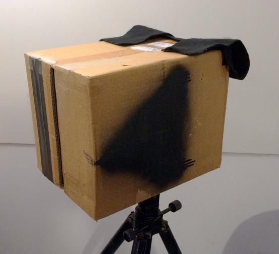
The project stars out with a corrugated cardboard box. The stiffer the board the better. The top or bottom can be removed (not both!). Along the remaining end a slit is cut running vertically from top to bottom of the box. This slit may be something like an inch or more wide. Along the inner side of that end where the slit is now you install black rectangular paper masks that are as long as the slit is. Glue them to the back of the inside of the box leaving a space of abut 1 millimeter or so between them. Since the slit you cut in the box was probably not very straight or smooth, these paper masks will allow you to make a slit that has both smooth and straight edges and is uniform in width along the length of the slit.
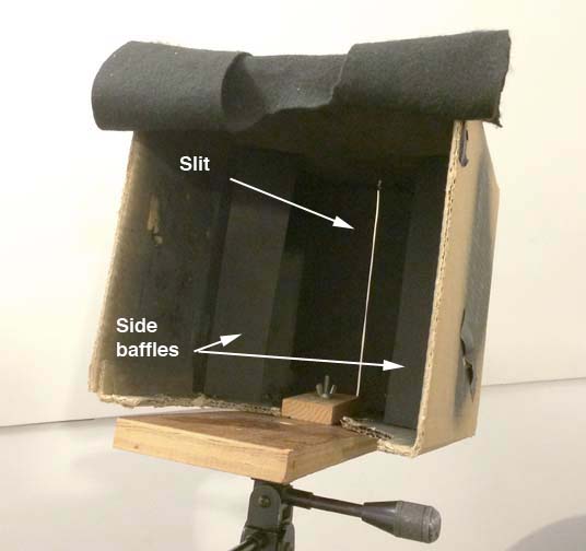
Someplace near the middle of the interior of the box and running in the same direction as the slit masks install a pair of paper baffles maybe a couple inches wide on each side of the box. The function of these baffles is to stop light coming in from the slit falling on the side of the box from being seen and recorded by the sensor in the camera.
I made a clamping device to attach the box to a sturdy wooden "platform" by way of a "T" nut installed in it the wooden platform could be securely fastened to a tripod or other support. The base platform also needs to support a camera rotation device plus the camera as well. Trying to attach the box itself to anything is probably a lost cause because of the flexibly and pliability of the cardboard - even if it is heavy duty. The cardboard box could even be glued to the stiff supporting platform but that makes the system a bit less portable.
The plans for my photographic oscilloscope or strip chart recorder are given below. No dimensions are critical. Follow the idea and not so much the details.
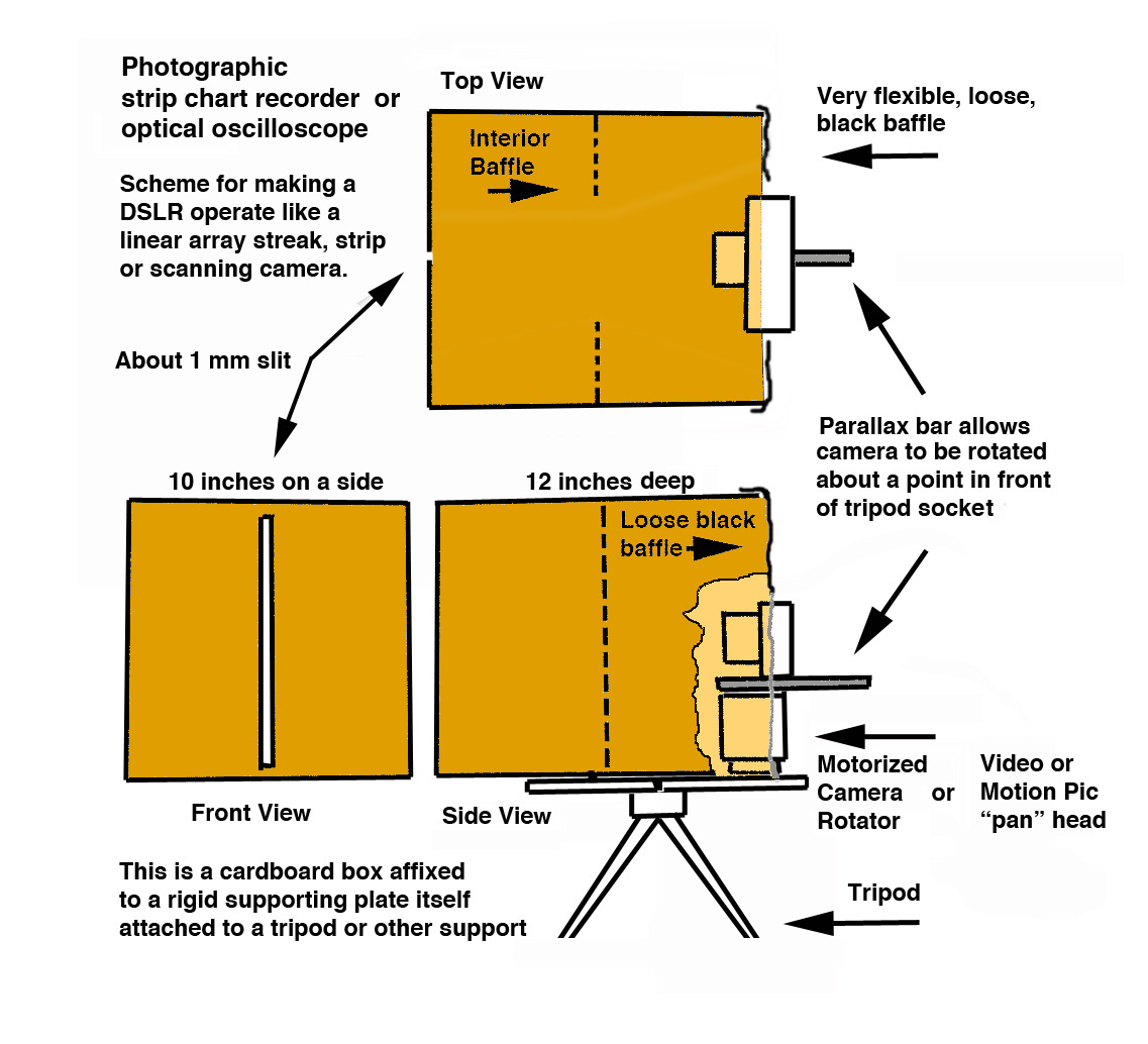
Above is the layout of the box that I made to make the DSLR
function as
a linear array recording device. Essentially it behaves as an optical
or
photographic strip chart recorder. But where the strip chart recorder
and even an oscilloscope are limited in the number of inputs, this
device is not limited in that way.
I attached the cardboard box to a wooden supporting plate because I wanted to attach the contraption to a tripod. A "T" nut fitting through the wooden support served this purpose.
What makes the system work is that the camera makes a record of the fine slit installed in the front of the box, and anything that it sees through that slit, wiping it across the focal plane of the camera by rotating the camera while the camera's shutter is open. It is that rotation that introduces the element of time into the final records.
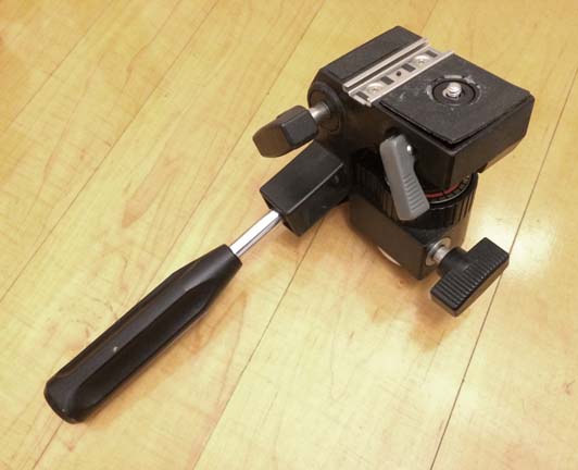
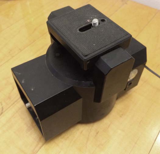
To rotate the camera several approaches could be taken. I am illustrating two of them. One is to use a common "pan" head attached to many motion picture and video tripods. Often these "heads" can be detached from even quite inexpensive such tripods. One of these is shown on the left.
Shown on the right is a second solution. It consists of a motorized rotational device or turntable to which the camera can be attached. In this case the device shown is specifically built to carry a camera but with a bit of improvisation something similar can be built from scratch.
In order to get the most out of this improvised system it is recommended that the camera be set-up in the same manner that as the camera is rotated objects near and far but included within the slit do not move with respect to each other. This can be accomplished by rotating the camera about a point forward of the tripod socket built into the camera body.
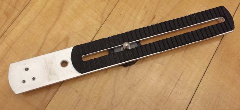
To accomplish this the camera is attached to a "parallax bar" such as shown here. It has a way to be attached to a 1/4 x 20 bolt such as on a tripod and it has a slot within which rides another bolt that fastens the camera to it.
Exactly where that "magical" point is is found by trial and error. Moving the camera back and forth along the bar and making a trial "run" so to speak. When near and far objects remain fixed with respect to each other as the camera pans and the image of the slit moves from side to side the camera is fixed at that location on the bar.
The "bar" or bracket you see here is a salvaged item as the three small holes on the left are the remains of whatever was attached there at some time. It might have been a connecting shoe for a flash.
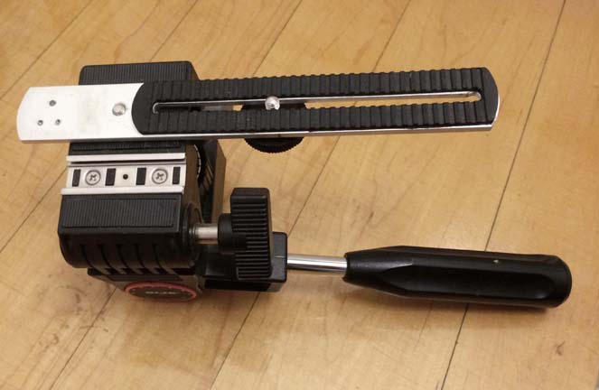
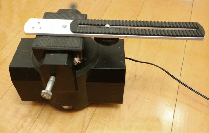
On the left you see the "parallax bar" attached to the photographic or video pan head. On the right it is attached to the motorized turntable device. In both cases you can see that the camera can be located on the "bar" at various distances from the point of attachment to the pan head or the turntable. This allows one to find that point at which if the camera is rotated objects located near and far from the camera, but falling within the slit, remain stationary with respect to each other.
There is an article that describes the making of a home-made parallax bar and its purpose. It is listed at the bottom of this article with the URL linking to it. But if you don't want to make one, metal brackets such as shown here or similar brackets designed to hold accessories next to a camera, are fairly readily obtainable. It used to be that photo stores would have them in their "junk" bins but it is hard to find such photo stores nowadays!
This is the finished assembly shown with the tripod pan head on the left and with the motorized panning devise holding up the camera on the right. If making the manually operated device the rate at which the camera rotates is just a function of how fast you rotate the camera. In the case of the motorized device the rotation rate is controlled by the voltage supplied to the DC motor that drives it.
When using this piece of equipment, with the camera aimed at the slit so that it falls right in the middle of the frame, you aim the slit so it covers the area of interest. Then you pan the camera to one side so that the slit leaves the field of view of the camera. Next step is to open the shutter for a time that is a bit longer than the time it will take the camera to pan over to the other side moving the image of the slit across the focal plane. In so doing the camera will record, over time, whatever the part of the subject that was covered by the slit did during that time.
Since the sensor of the camera will be recording not only the moving slit but also the interior of the box it is prudent to end up with good results to exclude as much light from finding its way into the box as possible. That is the function of the loosely hanging black felt baffle. Loose enough to not interfere with the camera rotation but tight fitting enough to stop some light at least from reaching the interior.
It also helps to spray paint the interior of the box flat black to help reduce unwanted stray light from bouncing around inside the box and lowering the quality of the records.
 To
add a
time base to the oscillographic records consider making
yourself a 100 Hz flashing LED such as shown in the photograph below.
There is an article available that explains how to make one using
relatively commonplace electronic components. If you include this
flashing LED at the bottom of the slit of the device you will get a
series of dots or marks spaced 1/100 second apart and you would then be
able to determine the duration of anything by simply counting the
number of dots from end to end of the image of your event.
To
add a
time base to the oscillographic records consider making
yourself a 100 Hz flashing LED such as shown in the photograph below.
There is an article available that explains how to make one using
relatively commonplace electronic components. If you include this
flashing LED at the bottom of the slit of the device you will get a
series of dots or marks spaced 1/100 second apart and you would then be
able to determine the duration of anything by simply counting the
number of dots from end to end of the image of your event.
The title of the article describing the LED flasher is: 100 Hz flashing LED source for timing applications and the URL is: http://people.rit.edu/andpph/text-LED-timing.html
Now here is a thought. If as you pan the camera and you also pan the tripod holding the camera you could make panoramic photographs. Not very long ones probably. Their length would depend on the lens that is fitted to the camera. The shorter the focal length of the lens the wider the possible angle of the resulting photo will be.
This is the first one I made in my kitchen area. The camera, on the motorized platform, was panned from side to side to effectively move the slit's image across the focal plane of the camera as described above. While the camera was rotating the camera and slit-box together were rotated, by hand, in the opposite direction that the camera was rotating. Part of the pan was cut off by the shutter closing before the image of the slit reached the far side of the image. Obviously the length of the panorama is limited by the width of the camera's sensor. The height of the panorama is limited by the height of the slit and eventually by the width of the sensor in the camera. Not a very practical thing to do but it is the process that is possibly of interest.
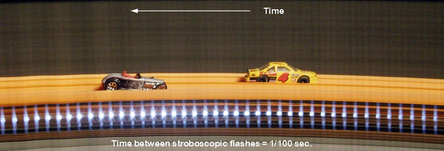
Below is an example of a photofinish photograph where the cars are racing down a ramp while the slit box remains stationary but the camera pans side to side turned by a motorized turntable. In this case the flashing LED was included in the photo to give a time base to the the resulting image.
You can also make peripheral or rollout photos with this device. Simply ask a subject to rotate in front of the stationary box while the camera pans. The result should be a photograph that shows your subject from the side, front, other side and maybe even the back. That is a rollout record. An example is shown on the left below.


All the previous photographs show the system operating in the "strip" mode. If you make a spring move up and down, photograph a ball bouncing (example shown above), or a sewing machine stitch, or an object rotate while seen through the slit you could make good estimates of stitching rate, bounce behavior, oscillation rate or rotation rate, especially if you include the light from the flashing LED mentioned earlier. In this case the camera would be operating in the "streak" mode.
You can find more reading material about this subject in the following articles:
Improvised or Salvaged Panoramic Rotation Axis Device
http://www.davidhazy.org/andpph/text-panoramic-bar.html
An optical strip chart recorder for classroom applications
http://www.davidhazy.org /andpph/TEXT-OPTICAL-STRIP-CHART-RECORDER-FOR-CLASSROOM-APPLICATONS.html
Applications for a DSLR used as a strip or streak camera
http://www.davidhazy.org/andpph/text-strip-streak-DSLR-aps.html
For more reading material about a variety of topics check out:
http://www.davidhazy.org/andpph/articles.html
If you have found this material of interest or if you have questions or constructive and helpful comments to share feel free to drop me a line.
Thank you,
Andrew Davidhazy
andpph@davidhazy.org.
Images for Science and Education
Strip chart recorders and oscilloscopes are very common instruments and are used in a wide variety of applications, from EKG recorders, to lie detectors, to seismographs, electrical signal display instruments of many sorts. They all suffer from limitations imposed by the fact that there are only so many pens that can be installed in a chart recorder and even oscilloscopes, the electronic equivalent of the strip chart recorder, are limited in the number of input signals they can monitor at any given time.
A photographic or optical strip chart recorder or photographic oscilloscope does not have such limitations. Since it records light many input signals can be accommodated in the final record. The record that strip chart recorders and oscilloscopes deliver is powerful because along one axis of the record the TIME element is included. Unlike regular photographs that produce a 2 dimensional record of a scene, strip chart recorders and oscilloscopes display what happened over a period of time. Only 1 dimension of space and but other dimension is time. Chart recorders and oscilloscopes include a time base of some kind so that accurate measurement of elapse time can be made form them. Thus one can determine such things as heart rate with and EKG, the period of oscillation of a moving spring, the period between tremors recorded by a seismograph, etc.
In this article the objective is to descriobe how to make a simple analog to these devices using nothing more than a standard DSLR camera and some relatively inexpensive and readily available parts. And if not available you are encouraged to improvise!
The project stars out with a corrugated cardboard box. The stiffer the board the better. The top or bottom can be removed (not both!). Along the remaining end a slit is cut running vertically from top to bottom of the box. This slit may be something like an inch or more wide. Along the inner side of that end where the slit is now you install black rectangular paper masks that are as long as the slit is. Glue them to the back of the inside of the box leaving a space of abut 1 millimeter or so between them. Since the slit you cut in the box was probably not very straight or smooth, these paper masks will allow you to make a slit that has both smooth and straight edges and is uniform in width along the length of the slit.
Someplace near the middle of the interior of the box and running in the same direction as the slit masks install a pair of paper baffles maybe a couple inches wide on each side of the box. The function of these baffles is to stop light coming in from the slit falling on the side of the box from being seen and recorded by the sensor in the camera.
I made a clamping device to attach the box to a sturdy wooden "platform" by way of a "T" nut installed in it the wooden platform could be securely fastened to a tripod or other support. The base platform also needs to support a camera rotation device plus the camera as well. Trying to attach the box itself to anything is probably a lost cause because of the flexibly and pliability of the cardboard - even if it is heavy duty. The cardboard box could even be glued to the stiff supporting platform but that makes the system a bit less portable.
The plans for my photographic oscilloscope or strip chart recorder are given below. No dimensions are critical. Follow the idea and not so much the details.
I attached the cardboard box to a wooden supporting plate because I wanted to attach the contraption to a tripod. A "T" nut fitting through the wooden support served this purpose.
What makes the system work is that the camera makes a record of the fine slit installed in the front of the box, and anything that it sees through that slit, wiping it across the focal plane of the camera by rotating the camera while the camera's shutter is open. It is that rotation that introduces the element of time into the final records.
To rotate the camera several approaches could be taken. I am illustrating two of them. One is to use a common "pan" head attached to many motion picture and video tripods. Often these "heads" can be detached from even quite inexpensive such tripods. One of these is shown on the left.
Shown on the right is a second solution. It consists of a motorized rotational device or turntable to which the camera can be attached. In this case the device shown is specifically built to carry a camera but with a bit of improvisation something similar can be built from scratch.
In order to get the most out of this improvised system it is recommended that the camera be set-up in the same manner that as the camera is rotated objects near and far but included within the slit do not move with respect to each other. This can be accomplished by rotating the camera about a point forward of the tripod socket built into the camera body.
To accomplish this the camera is attached to a "parallax bar" such as shown here. It has a way to be attached to a 1/4 x 20 bolt such as on a tripod and it has a slot within which rides another bolt that fastens the camera to it.
Exactly where that "magical" point is is found by trial and error. Moving the camera back and forth along the bar and making a trial "run" so to speak. When near and far objects remain fixed with respect to each other as the camera pans and the image of the slit moves from side to side the camera is fixed at that location on the bar.
The "bar" or bracket you see here is a salvaged item as the three small holes on the left are the remains of whatever was attached there at some time. It might have been a connecting shoe for a flash.
On the left you see the "parallax bar" attached to the photographic or video pan head. On the right it is attached to the motorized turntable device. In both cases you can see that the camera can be located on the "bar" at various distances from the point of attachment to the pan head or the turntable. This allows one to find that point at which if the camera is rotated objects located near and far from the camera, but falling within the slit, remain stationary with respect to each other.
There is an article that describes the making of a home-made parallax bar and its purpose. It is listed at the bottom of this article with the URL linking to it. But if you don't want to make one, metal brackets such as shown here or similar brackets designed to hold accessories next to a camera, are fairly readily obtainable. It used to be that photo stores would have them in their "junk" bins but it is hard to find such photo stores nowadays!
This is the finished assembly shown with the tripod pan head on the left and with the motorized panning devise holding up the camera on the right. If making the manually operated device the rate at which the camera rotates is just a function of how fast you rotate the camera. In the case of the motorized device the rotation rate is controlled by the voltage supplied to the DC motor that drives it.
When using this piece of equipment, with the camera aimed at the slit so that it falls right in the middle of the frame, you aim the slit so it covers the area of interest. Then you pan the camera to one side so that the slit leaves the field of view of the camera. Next step is to open the shutter for a time that is a bit longer than the time it will take the camera to pan over to the other side moving the image of the slit across the focal plane. In so doing the camera will record, over time, whatever the part of the subject that was covered by the slit did during that time.
Since the sensor of the camera will be recording not only the moving slit but also the interior of the box it is prudent to end up with good results to exclude as much light from finding its way into the box as possible. That is the function of the loosely hanging black felt baffle. Loose enough to not interfere with the camera rotation but tight fitting enough to stop some light at least from reaching the interior.
It also helps to spray paint the interior of the box flat black to help reduce unwanted stray light from bouncing around inside the box and lowering the quality of the records.
To
add a
time base to the oscillographic records consider making
yourself a 100 Hz flashing LED such as shown in the photograph below.
There is an article available that explains how to make one using
relatively commonplace electronic components. If you include this
flashing LED at the bottom of the slit of the device you will get a
series of dots or marks spaced 1/100 second apart and you would then be
able to determine the duration of anything by simply counting the
number of dots from end to end of the image of your event. The title of the article describing the LED flasher is: 100 Hz flashing LED source for timing applications and the URL is: http://people.rit.edu/andpph/text-LED-timing.html
Now here is a thought. If as you pan the camera and you also pan the tripod holding the camera you could make panoramic photographs. Not very long ones probably. Their length would depend on the lens that is fitted to the camera. The shorter the focal length of the lens the wider the possible angle of the resulting photo will be.
This is the first one I made in my kitchen area. The camera, on the motorized platform, was panned from side to side to effectively move the slit's image across the focal plane of the camera as described above. While the camera was rotating the camera and slit-box together were rotated, by hand, in the opposite direction that the camera was rotating. Part of the pan was cut off by the shutter closing before the image of the slit reached the far side of the image. Obviously the length of the panorama is limited by the width of the camera's sensor. The height of the panorama is limited by the height of the slit and eventually by the width of the sensor in the camera. Not a very practical thing to do but it is the process that is possibly of interest.
Below is an example of a photofinish photograph where the cars are racing down a ramp while the slit box remains stationary but the camera pans side to side turned by a motorized turntable. In this case the flashing LED was included in the photo to give a time base to the the resulting image.
You can also make peripheral or rollout photos with this device. Simply ask a subject to rotate in front of the stationary box while the camera pans. The result should be a photograph that shows your subject from the side, front, other side and maybe even the back. That is a rollout record. An example is shown on the left below.
All the previous photographs show the system operating in the "strip" mode. If you make a spring move up and down, photograph a ball bouncing (example shown above), or a sewing machine stitch, or an object rotate while seen through the slit you could make good estimates of stitching rate, bounce behavior, oscillation rate or rotation rate, especially if you include the light from the flashing LED mentioned earlier. In this case the camera would be operating in the "streak" mode.
You can find more reading material about this subject in the following articles:
Improvised or Salvaged Panoramic Rotation Axis Device
http://www.davidhazy.org/andpph/text-panoramic-bar.html
An optical strip chart recorder for classroom applications
http://www.davidhazy.org /andpph/TEXT-OPTICAL-STRIP-CHART-RECORDER-FOR-CLASSROOM-APPLICATONS.html
Applications for a DSLR used as a strip or streak camera
http://www.davidhazy.org/andpph/text-strip-streak-DSLR-aps.html
For more reading material about a variety of topics check out:
http://www.davidhazy.org/andpph/articles.html
If you have found this material of interest or if you have questions or constructive and helpful comments to share feel free to drop me a line.
Thank you,
Andrew Davidhazy
andpph@davidhazy.org.