Applications
for a DSLR used as a strip or streak camera
Andrew Davidhazy
Images for Science and Education
Images for Science and Education
Based on a previous
article that described how to set-up an improvised strip (or streak)
image recording system based on a particular way of arranging the
camera, the subject and an intervening slot now we'll talk about
applications.
The strip camera as a photofinish camera
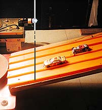
Determining the order of finish of participants in races is a difficult task when it comes to making time difference determinations that are less than a second or so long. In this example the objective is to determine the difference in the time of arrival at a "finish line" between two Matchbox race cars rolling down an inclined ramp.
First a line across the track needs to be identified as the finish line and it may be marked by a ruler across the track or a marker on the side closest and farthest from the camera. The edge of the ruler or those two markers identifying the finish line must, of course, be visible through the slot in the black curtain from the camera's point of view. As the camera and lens are rotated the ruler's edge or the two markers on the track must remain within the slot.
A timing light of some kind, such as a stroboscope flashing at some known rate, should be included within the slot if accurate timing information is desired. If all one wants to find out is which car finished first then the timing light is not needed.
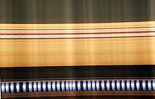
It becomes obvious that if the camera is not turned at an even speed the resulting image is going to show variations in brightness or "banding" as shown in the illustration below. Not only are there brightness variations but the spacing of the light flashes from the stroboscope indicate that the rate at which the image of the slot moved across the viewfinder of the camera was not even. This is a common problem associated with "strip" type of cameras and should not be cause for dismay.
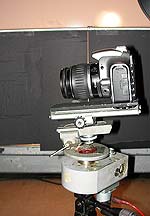
 Although
the camera can be rotated "by hand" as described above, to
end up with as "band free" a record as possible the use of a
motorized drive for rotating the camera is probably necessary. This
device should provide a consistent rotation rate of the camera. A
motorized head
was used for the photofinish photographs shown here. The
motorized head used for this application is a worm gear driven,
high torque, "platform" holding the camera and driven by a
small DC motor at rates variable from between 1 revolution every 5 to
30 seconds or so.
Although
the camera can be rotated "by hand" as described above, to
end up with as "band free" a record as possible the use of a
motorized drive for rotating the camera is probably necessary. This
device should provide a consistent rotation rate of the camera. A
motorized head
was used for the photofinish photographs shown here. The
motorized head used for this application is a worm gear driven,
high torque, "platform" holding the camera and driven by a
small DC motor at rates variable from between 1 revolution every 5 to
30 seconds or so.
The camera needs to be rotated in the same direction as the cars are going to be moving. In this illustration the cars were moving from left to right down the ramp so the camera was turned clockwise.
Since the cars pass by the slot (which defines the finish line) in a very short time the camera also must be turned quite rapidly in order to catch them as they sequentially pass over the finish line. A couple of people could perform this project by one of them turning the camera and operating the camera shutter while the other one lets go of the cars at the appropriate time.
To capture a "photofinish" record the camera is aimed first to the left of the slot. Then one person needs to activate the camera shutter at the time the camera gets into position for the recording to start and the cars need to be released either slightly ahead of this time or later. This depends on how fast the camera will be turning and the time it takes the cars to get to the bottom of the ramp. Experience or trial-and-error will be the guiding factor.
While the cars are racing to the bottom of the ramp, and over the finish line, the image of the slot passes from one side of the viewfinder to the other. Then the shutter is closed.
An examination of the record will indicate if the rate at which the camera was turned was appropriate for the speed at which the car(s) were moving. If the cars appear to be compressed as shown in the illustration below the camera was rotated too slowly. If the cars appear to be stretched and appear to be longer than what they in reality then the camera was turned too rapidly.
 The flashing light source should
appear as a
series of "blips" along
the record. One can tell how long it took for the image of the slot to
pass across the viewfinder by counting the number of marks left by the
flashing light. In the (cropped) illustration of the single car the
flashing rate was 10 flashes a
second and so the horizontal dimension of the image represents a total
time of about 2.5/10ths of a second.
The flashing light source should
appear as a
series of "blips" along
the record. One can tell how long it took for the image of the slot to
pass across the viewfinder by counting the number of marks left by the
flashing light. In the (cropped) illustration of the single car the
flashing rate was 10 flashes a
second and so the horizontal dimension of the image represents a total
time of about 2.5/10ths of a second.
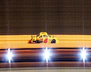
Regardless of whether the images of the cars appear compressed, normal looking or stretched, the order of finish will be indisputably determined by this method. The one closest to the edge towards which the cars appear to be moving is the winner of the race (assuming the cars are moving in the direction their engines are located!). The amount of time that elapsed between the arrival to the finish line of the first car and the second car can be determined by the number of light flashes between the front end of the first car and that of the second.

The finished product should look something like the attached illustration. In this record the stroboscope was flashing at a rate of 100 flashes per second so the time between marks is 1/100 second. Counting the number of flashes from the front end of the yellow car to the front of the silver one one can count 14 marks and so the time difference between the arrival of the yellow compared to the silver is 14/100 of a second. Undoubtedly much more accurate then trying to determine this time interval by estimation. And if the finish disparity had been less it would be even more difficult. It would even be possible to time to intervals of less than 1/100 second by splitting the interval for 1/100 second into the desired fractional parts.
All in all a very sophisticated and reliable timing system I hope you agree!
The strip camera as a peripheral or roll out camera
 This
assumes that one is interested in capturing an image of some
subject so that all sides of the subject are included on one flat
continuous representation of the features on the surface of the
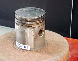
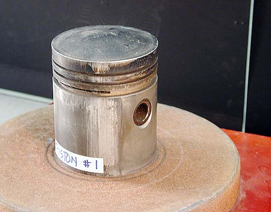
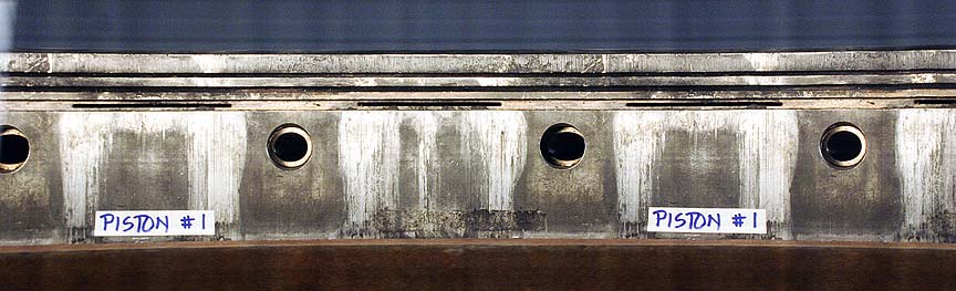
subject. A typical subject is something like a piston that exhibits
wear on its surface and where it would be desirable to show the wear
pattern as a function of rotation around the periphery of the object.
This
assumes that one is interested in capturing an image of some
subject so that all sides of the subject are included on one flat
continuous representation of the features on the surface of the
subject. A typical subject is something like a piston that exhibits
wear on its surface and where it would be desirable to show the wear
pattern as a function of rotation around the periphery of the object.
Normally one would make three, four or more photographs from different points of view around the piston and then have the recipient leaf through the images identifying the problem areas.
A peripheral, or rollout, record allows all defects to be visible at a glance. To make such images
a strip camera is normally used. An alternative is to make several 2D records, cut out the central portion of a series of images and then "stitch" them together into a continuous record. Film type strip cameras accomplish all this by recording the moving features of a rotating subject through a slit onto film matched to move at the same rate as the image of the object moves.
Linear array type strip cameras do essentially the same thing but they are quite expensive and for occasional use maybe not the best investment especially if one is willing to tolerate a less than perfection in the final result.
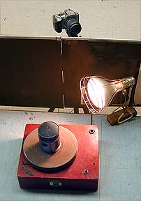 Setting
up the "improvised"
strip (and streak)
camera as shown in the illustration allows a photographer to make
peripheral records that are probably suitable for most purposes. As
described earlier all one needs is a mask with a slot cut into it and a
turntable to rotate the object. A motorized method for turning the
camera is useful but not absolutely necessary. It all depends on the
degree of perfection desired!
Setting
up the "improvised"
strip (and streak)
camera as shown in the illustration allows a photographer to make
peripheral records that are probably suitable for most purposes. As
described earlier all one needs is a mask with a slot cut into it and a
turntable to rotate the object. A motorized method for turning the
camera is useful but not absolutely necessary. It all depends on the
degree of perfection desired!
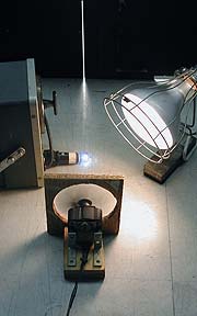
The camera is set up on one side of the black curtain or mask and aligned so that the center of rotation of the turntable falls within the slot in the curtain and the camera/lens combination is rotated about a point that does not cause that center of rotation to move out of the slot as the camera turns.
For an initial set-up before the mask is placed in front of the camera the object under study is placed and centered on the turntable and the lens of the camera focused on its surface. The reason for this is that after the camera "looks" at the subject once the slot is in place it is quite difficult to judge the accuracy of focus.
The, once the mask with the slot is placed between the camera and the turntable a thin vertical object is placed over the turntable center. Something like a marker that can stand on one end will do. This is then sighted through the camera's viewfinder and its position tracked as the image of the slot moves from one side of the viewfinder to the other by virtue of the camera turning.
Once this is adjusted then the object of study, in this case Piston #1, is placed and centered on the turntable. Noting that a standard turntable rotates the piston in a clockwise direction the camera is adjusted so that it rotates in a counterclockwise direction. The exposure time is adjusted so that it is the a bit longer than it takes the image of the slot to traverse the camera's viewfinder.
This ensures the least "fogging" effect from the black sides of the mask which the camera is aimed at all the time that the image of the slot travels across the viewfinder.
The rate at which the camera turns determines a number of things. For one, the exposure time that any local spot of the recorded image gets. This affects the choice of sensor speed or aperture that one needs to use to secure a useful record.
It also determines whether the aspect ration of the reproduction matches that of the original. For a high quality reproduction not only has the subject to be accurately centered but the reproduction must have the same ratio of height to length as the original subject has in terms of height to circumference.
In the digital world there is the possibility of adjusting the aspect ration of the reproduction within limits and this is something that film systems were not able to do well.
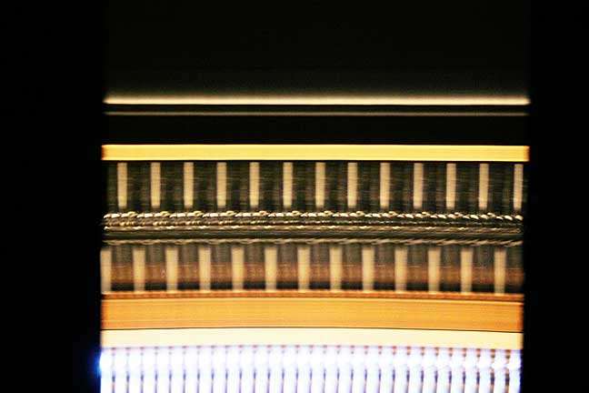
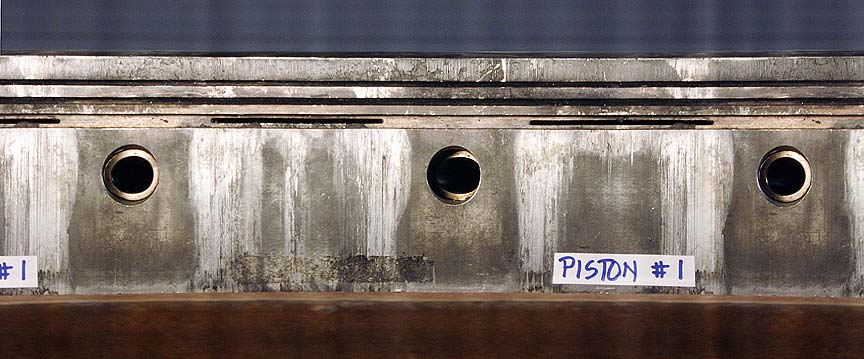
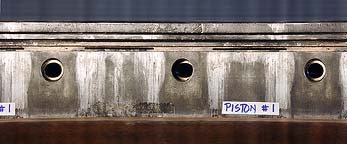 The first
periphotograph
was made
with the camera lens set to 45 mm focal length and it shows slightly
over 360 degrees of the surface of the piston in question.
The first
periphotograph
was made
with the camera lens set to 45 mm focal length and it shows slightly
over 360 degrees of the surface of the piston in question.
If the reproduction is slightly off in terms of appropriate reproduction ratio the horizontal dimension of a record can be adjusted by digital image management removing constraints on vertical / horizontal proportions or the focal length of the camera lens can be adjusted and the rotation speed of the camera changed. Selecting a shorter focal length will reduce the vertical dimension of the subject and also allow more revolutions of the turntable to be recorded.
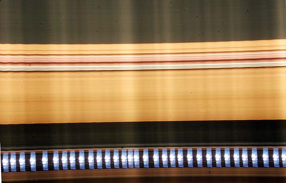
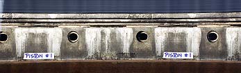 This is shown in the second periphotograph
made
at 35 mm focal length. It was possible to record more revolutions of
the piston and adjust the rotation rate of the camera to produce a
proportionally slightly longer image of each 360 degree rotation of the
piston than with the longer focal length setting which would not be
able to fit a 360 degree turn within the available space for a single
exposure
of the camera.
This is shown in the second periphotograph
made
at 35 mm focal length. It was possible to record more revolutions of
the piston and adjust the rotation rate of the camera to produce a
proportionally slightly longer image of each 360 degree rotation of the
piston than with the longer focal length setting which would not be
able to fit a 360 degree turn within the available space for a single
exposure
of the camera.
There are many applications for peripheral or rollout photography and this simplified approach may be useful in many situations from photography of archeological specimens to hoky photographic caricatures of human subjects.
The strip camera used as a streak camera
Above we have considered the case where the subject moves across the slot. It is also possible to acquire useful position vs. elapsed time information about a subject for the purpose of making estimations of such factors as event duration, simultaneity velocity, rotation rate, etc. Any factor where timing is involved.
In this case the strip camera will function as a "streak" camera. It is analogous to the ubiquitous strip chart recorder except that where the chart generally recorder uses pens to track some aspect of an event of subject, the streak camera uses light to accomplish the same thing.
By now the assumption is made that setting up the camera and slot through which the camera makes a record of some kind has been covered in great enough detail it does not need to be repeated.
The application of the system for a couple of timing applications will be described on the other side of the slot by 2 specific applications. The first one entails visualizing the bounce performance of a ping-pong ball, to determine the height of each bounce and the difference in height from one bounce to the next and to hint at the additional information regarding ball velocity that can be extracted from the resulting images. The second application describes and illustrates the method by which rotation rate can be determined based on two distinct variations of the streak photography technique.
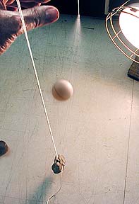
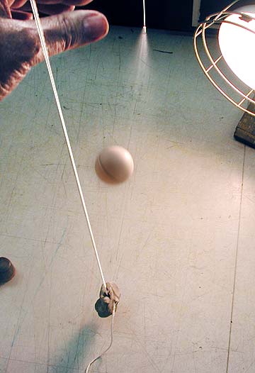
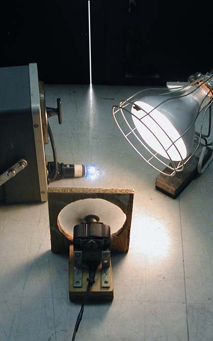
As shown in the figure at left the camera is lined up in such a manner that it can detect the full length of the white string along the slot between it and the camera lens as the image of the slot is made to travel across the camera's viewfinder.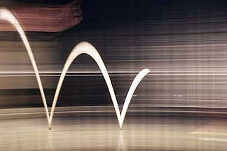
Then, as the camera is turning and is about to detect the slot the shutter is opened and the ball is
dropped so that it falls along the length of the slot and later it continues to bounce without leaving the slot.
As shown in the figure at the right this is a lot easier said than done.
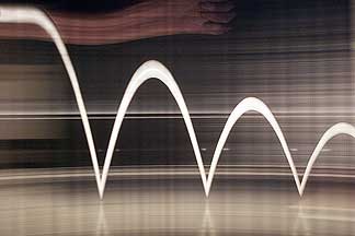
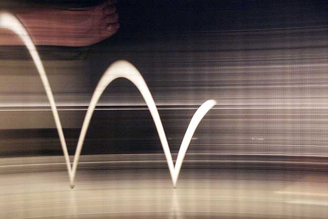
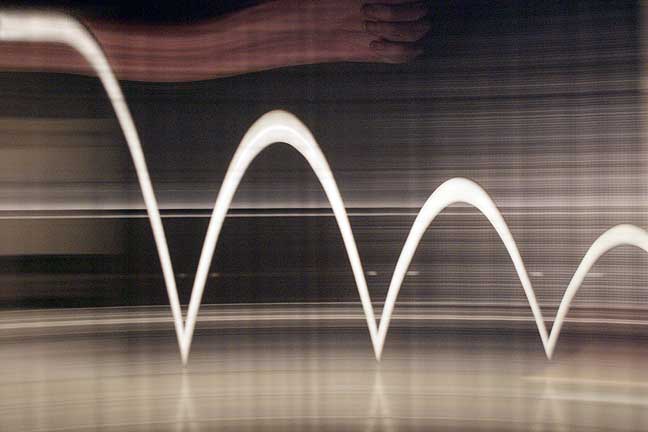
Invariably the ball bounces off course or the shutter closes prematurely or too late, etc. but with repeated tries and a bit of luck a record of ball position vs. time extending across the full width of the camera's sensor can be obtained. It might look like the photographs shown below. At the far left the ball is being held still and so it leaves a horizontal "streak" of its position. When the ball is released it accelerates to the tabletop and then it bounces up, loosing speed until it momentarily is still but immediately it resumes its down ward path accelerating again on the downside. With each bounce it loses some of its energy and can not reach the same height as for the previous bounce.
It is easily possible to determine the
distance that the ball was
dropped from and the height of each bounce by using the ball itself as
the device that gives scale to the image. Of course some other object
could have been included in the photograph to give a sense of scale but
in this case we can use the subject itself as the scale providing
object.
Assuming that the ping-pong ball measures 30 mm in diameter one can determine that the height from which the ball was dropped is about 13 inches from the tabletop (measuring from the top of the ball). Then measuring the height of the traces related to each bounce indicates that the height of the first bounce was only 10.05 inches, the third 7.92 inches and the third 6.45 inches. Therefore at the first bounce it lost 13.16 -10.05 or 3.11 inches. Between the first bounce and the second it lost 10.05 - 7.92 or 2.13 inches and between the second and third 7.92 - 6.45 or 1.47 inches. This kind of quantitative result would be very difficult to obtain by other means. The continuous recording capability over time of the streak camera is what makes this possible.
What is not possible to determine from this photograph is the length of time between bounces. This could have been determined if some standard reference of time (such as a stroboscope or a subject rotating at some known rate had been included in the photograph. This will be treated in the next example.

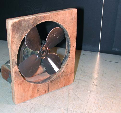
 In this case it
is
desired to find out the rotation rate of a fan. Granted that there are
many methods available to do this but the decision here is to base it
on the use of a steak photography system. The fan has one blade painted
with a white stripe so that it can be used as a marker that will
provide position information as the fan is rotating. The shaft of the
fan is lined up with the camera so that it remains visible through the
slot between the two as the camera is rotated. Additionally, in this
case the flashes from a stroboscope flashing at 100 flashes per second
are included so they are visible through the slot also.
In this case it
is
desired to find out the rotation rate of a fan. Granted that there are
many methods available to do this but the decision here is to base it
on the use of a steak photography system. The fan has one blade painted
with a white stripe so that it can be used as a marker that will
provide position information as the fan is rotating. The shaft of the
fan is lined up with the camera so that it remains visible through the
slot between the two as the camera is rotated. Additionally, in this
case the flashes from a stroboscope flashing at 100 flashes per second
are included so they are visible through the slot also.
Now the camera is simply rotated about its rear nodal point and the shutter opened just before the image of the slot reaches the edge of the viewfinder and closed after it passes the other edge. This is generally accomplished by setting the camera shutter to some specific exposure time so that one does not have to worry about when to close the shutter only when to open it. With a bit of patience and luck eventually it should be possible to acquire an image that might look similar to the one below.
 The camera in this case
was turned
quite rapidly but t is obvious that the marked blade was at the 12
o'clock position every once in a while and that between these instances
it was at the 6 o'clock position indicating it had moved 180 degrees.
Between upright images of the marked blade the other, dark, blades can
also be detected. Three of them as it should be.
The camera in this case
was turned
quite rapidly but t is obvious that the marked blade was at the 12
o'clock position every once in a while and that between these instances
it was at the 6 o'clock position indicating it had moved 180 degrees.
Between upright images of the marked blade the other, dark, blades can
also be detected. Three of them as it should be.
To determine the rate of rotation of the fan one needs to merely select an arbitrary number of upright marks and count the number of 1/100 second light flashes between these marks minus 1 and the rate is then number of rotations divided by elapsed time. In this instance, taking the first mark to the left as "time zero" there are 10 upright marks visible reaching the right edge of the photograph. Counting timing marks for the same distance one can count 23 of them. So 10 turn in 23/100 second or 43.48 rps or 2608 rpm.
The rate of rotation of the fan can also be determined by using the camera shutter itself as a timing device. After all, camera manufactures spend a great deal of effort in making sure that the camera shutters deliver known amounts of exposure time to their sensors.
 To determine the
rotation rate based
on camera exposure time one needs to make sure that the shutter
operates in less time than it takes the slot to sweep across the
viewfinder of the camera. One has to "catch" the slot as it's
image moves across the viewfinder and make sure to include both the
beginning and end of the shutter operation. This is shown in the
photograph on the left.
To determine the
rotation rate based
on camera exposure time one needs to make sure that the shutter
operates in less time than it takes the slot to sweep across the
viewfinder of the camera. One has to "catch" the slot as it's
image moves across the viewfinder and make sure to include both the
beginning and end of the shutter operation. This is shown in the
photograph on the left.
The exposure time set on the camera was 1/4 second. Within the two edges f the image one can count thirteen vertical marks. If one takes the first one as "time zero" then there are 12 marks indicating that the fan turned turned 12 times in 1/4 second. This results in 48 revolutions in one second or 2880 in one minute.
The two methods are in fairly close agreement. The discrepancy could be due to the shutter not delivering exactly a 1/4 second exposure time but considering that it comes built into a camera and is nowhere as specialized or expensive an instruments as a calibrated stroboscope the slight error is probably tolerable.
I hope that the above examples give you ideas for even more applications. The performance of springs, the vibration rate of tuning forks or those of guitar strings, etc. can all be examined with a streak recording system.
As a final note I must mention that the images you see illustrating this article were all improved compared to the raw files provided by the camera. Most were underexposed so had to be lightened using commonplace image processing software.
If you have found this material of interest or if you have questions or constructive and helpful comments to share feel free to drop me a line.
The strip camera as a photofinish camera
Determining the order of finish of participants in races is a difficult task when it comes to making time difference determinations that are less than a second or so long. In this example the objective is to determine the difference in the time of arrival at a "finish line" between two Matchbox race cars rolling down an inclined ramp.
First a line across the track needs to be identified as the finish line and it may be marked by a ruler across the track or a marker on the side closest and farthest from the camera. The edge of the ruler or those two markers identifying the finish line must, of course, be visible through the slot in the black curtain from the camera's point of view. As the camera and lens are rotated the ruler's edge or the two markers on the track must remain within the slot.


A timing light of some kind, such as a stroboscope flashing at some known rate, should be included within the slot if accurate timing information is desired. If all one wants to find out is which car finished first then the timing light is not needed.
It becomes obvious that if the camera is not turned at an even speed the resulting image is going to show variations in brightness or "banding" as shown in the illustration below. Not only are there brightness variations but the spacing of the light flashes from the stroboscope indicate that the rate at which the image of the slot moved across the viewfinder of the camera was not even. This is a common problem associated with "strip" type of cameras and should not be cause for dismay.
 Although
the camera can be rotated "by hand" as described above, to
end up with as "band free" a record as possible the use of a
motorized drive for rotating the camera is probably necessary. This
device should provide a consistent rotation rate of the camera. A
motorized head
was used for the photofinish photographs shown here. The
motorized head used for this application is a worm gear driven,
high torque, "platform" holding the camera and driven by a
small DC motor at rates variable from between 1 revolution every 5 to
30 seconds or so.
Although
the camera can be rotated "by hand" as described above, to
end up with as "band free" a record as possible the use of a
motorized drive for rotating the camera is probably necessary. This
device should provide a consistent rotation rate of the camera. A
motorized head
was used for the photofinish photographs shown here. The
motorized head used for this application is a worm gear driven,
high torque, "platform" holding the camera and driven by a
small DC motor at rates variable from between 1 revolution every 5 to
30 seconds or so.The camera needs to be rotated in the same direction as the cars are going to be moving. In this illustration the cars were moving from left to right down the ramp so the camera was turned clockwise.
Since the cars pass by the slot (which defines the finish line) in a very short time the camera also must be turned quite rapidly in order to catch them as they sequentially pass over the finish line. A couple of people could perform this project by one of them turning the camera and operating the camera shutter while the other one lets go of the cars at the appropriate time.
To capture a "photofinish" record the camera is aimed first to the left of the slot. Then one person needs to activate the camera shutter at the time the camera gets into position for the recording to start and the cars need to be released either slightly ahead of this time or later. This depends on how fast the camera will be turning and the time it takes the cars to get to the bottom of the ramp. Experience or trial-and-error will be the guiding factor.
While the cars are racing to the bottom of the ramp, and over the finish line, the image of the slot passes from one side of the viewfinder to the other. Then the shutter is closed.
An examination of the record will indicate if the rate at which the camera was turned was appropriate for the speed at which the car(s) were moving. If the cars appear to be compressed as shown in the illustration below the camera was rotated too slowly. If the cars appear to be stretched and appear to be longer than what they in reality then the camera was turned too rapidly.
 The flashing light source should
appear as a
series of "blips" along
the record. One can tell how long it took for the image of the slot to
pass across the viewfinder by counting the number of marks left by the
flashing light. In the (cropped) illustration of the single car the
flashing rate was 10 flashes a
second and so the horizontal dimension of the image represents a total
time of about 2.5/10ths of a second.
The flashing light source should
appear as a
series of "blips" along
the record. One can tell how long it took for the image of the slot to
pass across the viewfinder by counting the number of marks left by the
flashing light. In the (cropped) illustration of the single car the
flashing rate was 10 flashes a
second and so the horizontal dimension of the image represents a total
time of about 2.5/10ths of a second.Regardless of whether the images of the cars appear compressed, normal looking or stretched, the order of finish will be indisputably determined by this method. The one closest to the edge towards which the cars appear to be moving is the winner of the race (assuming the cars are moving in the direction their engines are located!). The amount of time that elapsed between the arrival to the finish line of the first car and the second car can be determined by the number of light flashes between the front end of the first car and that of the second.
The finished product should look something like the attached illustration. In this record the stroboscope was flashing at a rate of 100 flashes per second so the time between marks is 1/100 second. Counting the number of flashes from the front end of the yellow car to the front of the silver one one can count 14 marks and so the time difference between the arrival of the yellow compared to the silver is 14/100 of a second. Undoubtedly much more accurate then trying to determine this time interval by estimation. And if the finish disparity had been less it would be even more difficult. It would even be possible to time to intervals of less than 1/100 second by splitting the interval for 1/100 second into the desired fractional parts.
All in all a very sophisticated and reliable timing system I hope you agree!
The strip camera as a peripheral or roll out camera
 This
assumes that one is interested in capturing an image of some
subject so that all sides of the subject are included on one flat
continuous representation of the features on the surface of the
subject. A typical subject is something like a piston that exhibits
wear on its surface and where it would be desirable to show the wear
pattern as a function of rotation around the periphery of the object.
This
assumes that one is interested in capturing an image of some
subject so that all sides of the subject are included on one flat
continuous representation of the features on the surface of the
subject. A typical subject is something like a piston that exhibits
wear on its surface and where it would be desirable to show the wear
pattern as a function of rotation around the periphery of the object. Normally one would make three, four or more photographs from different points of view around the piston and then have the recipient leaf through the images identifying the problem areas.
A peripheral, or rollout, record allows all defects to be visible at a glance. To make such images
a strip camera is normally used. An alternative is to make several 2D records, cut out the central portion of a series of images and then "stitch" them together into a continuous record. Film type strip cameras accomplish all this by recording the moving features of a rotating subject through a slit onto film matched to move at the same rate as the image of the object moves.
Linear array type strip cameras do essentially the same thing but they are quite expensive and for occasional use maybe not the best investment especially if one is willing to tolerate a less than perfection in the final result.
Setting
up the "improvised"
strip (and streak)
camera as shown in the illustration allows a photographer to make
peripheral records that are probably suitable for most purposes. As
described earlier all one needs is a mask with a slot cut into it and a
turntable to rotate the object. A motorized method for turning the
camera is useful but not absolutely necessary. It all depends on the
degree of perfection desired!The camera is set up on one side of the black curtain or mask and aligned so that the center of rotation of the turntable falls within the slot in the curtain and the camera/lens combination is rotated about a point that does not cause that center of rotation to move out of the slot as the camera turns.
For an initial set-up before the mask is placed in front of the camera the object under study is placed and centered on the turntable and the lens of the camera focused on its surface. The reason for this is that after the camera "looks" at the subject once the slot is in place it is quite difficult to judge the accuracy of focus.
The, once the mask with the slot is placed between the camera and the turntable a thin vertical object is placed over the turntable center. Something like a marker that can stand on one end will do. This is then sighted through the camera's viewfinder and its position tracked as the image of the slot moves from one side of the viewfinder to the other by virtue of the camera turning.
Once this is adjusted then the object of study, in this case Piston #1, is placed and centered on the turntable. Noting that a standard turntable rotates the piston in a clockwise direction the camera is adjusted so that it rotates in a counterclockwise direction. The exposure time is adjusted so that it is the a bit longer than it takes the image of the slot to traverse the camera's viewfinder.
This ensures the least "fogging" effect from the black sides of the mask which the camera is aimed at all the time that the image of the slot travels across the viewfinder.
The rate at which the camera turns determines a number of things. For one, the exposure time that any local spot of the recorded image gets. This affects the choice of sensor speed or aperture that one needs to use to secure a useful record.
It also determines whether the aspect ration of the reproduction matches that of the original. For a high quality reproduction not only has the subject to be accurately centered but the reproduction must have the same ratio of height to length as the original subject has in terms of height to circumference.
In the digital world there is the possibility of adjusting the aspect ration of the reproduction within limits and this is something that film systems were not able to do well.
 The first
periphotograph
was made
with the camera lens set to 45 mm focal length and it shows slightly
over 360 degrees of the surface of the piston in question.
The first
periphotograph
was made
with the camera lens set to 45 mm focal length and it shows slightly
over 360 degrees of the surface of the piston in question. If the reproduction is slightly off in terms of appropriate reproduction ratio the horizontal dimension of a record can be adjusted by digital image management removing constraints on vertical / horizontal proportions or the focal length of the camera lens can be adjusted and the rotation speed of the camera changed. Selecting a shorter focal length will reduce the vertical dimension of the subject and also allow more revolutions of the turntable to be recorded.
 This is shown in the second periphotograph
made
at 35 mm focal length. It was possible to record more revolutions of
the piston and adjust the rotation rate of the camera to produce a
proportionally slightly longer image of each 360 degree rotation of the
piston than with the longer focal length setting which would not be
able to fit a 360 degree turn within the available space for a single
exposure
of the camera.
This is shown in the second periphotograph
made
at 35 mm focal length. It was possible to record more revolutions of
the piston and adjust the rotation rate of the camera to produce a
proportionally slightly longer image of each 360 degree rotation of the
piston than with the longer focal length setting which would not be
able to fit a 360 degree turn within the available space for a single
exposure
of the camera.There are many applications for peripheral or rollout photography and this simplified approach may be useful in many situations from photography of archeological specimens to hoky photographic caricatures of human subjects.
The strip camera used as a streak camera
Above we have considered the case where the subject moves across the slot. It is also possible to acquire useful position vs. elapsed time information about a subject for the purpose of making estimations of such factors as event duration, simultaneity velocity, rotation rate, etc. Any factor where timing is involved.
In this case the strip camera will function as a "streak" camera. It is analogous to the ubiquitous strip chart recorder except that where the chart generally recorder uses pens to track some aspect of an event of subject, the streak camera uses light to accomplish the same thing.
By now the assumption is made that setting up the camera and slot through which the camera makes a record of some kind has been covered in great enough detail it does not need to be repeated.
The application of the system for a couple of timing applications will be described on the other side of the slot by 2 specific applications. The first one entails visualizing the bounce performance of a ping-pong ball, to determine the height of each bounce and the difference in height from one bounce to the next and to hint at the additional information regarding ball velocity that can be extracted from the resulting images. The second application describes and illustrates the method by which rotation rate can be determined based on two distinct variations of the streak photography technique.
As shown in the figure at left the camera is lined up in such a manner that it can detect the full length of the white string along the slot between it and the camera lens as the image of the slot is made to travel across the camera's viewfinder.
Then, as the camera is turning and is about to detect the slot the shutter is opened and the ball is
dropped so that it falls along the length of the slot and later it continues to bounce without leaving the slot.
As shown in the figure at the right this is a lot easier said than done.
Invariably the ball bounces off course or the shutter closes prematurely or too late, etc. but with repeated tries and a bit of luck a record of ball position vs. time extending across the full width of the camera's sensor can be obtained. It might look like the photographs shown below. At the far left the ball is being held still and so it leaves a horizontal "streak" of its position. When the ball is released it accelerates to the tabletop and then it bounces up, loosing speed until it momentarily is still but immediately it resumes its down ward path accelerating again on the downside. With each bounce it loses some of its energy and can not reach the same height as for the previous bounce.
Assuming that the ping-pong ball measures 30 mm in diameter one can determine that the height from which the ball was dropped is about 13 inches from the tabletop (measuring from the top of the ball). Then measuring the height of the traces related to each bounce indicates that the height of the first bounce was only 10.05 inches, the third 7.92 inches and the third 6.45 inches. Therefore at the first bounce it lost 13.16 -10.05 or 3.11 inches. Between the first bounce and the second it lost 10.05 - 7.92 or 2.13 inches and between the second and third 7.92 - 6.45 or 1.47 inches. This kind of quantitative result would be very difficult to obtain by other means. The continuous recording capability over time of the streak camera is what makes this possible.
What is not possible to determine from this photograph is the length of time between bounces. This could have been determined if some standard reference of time (such as a stroboscope or a subject rotating at some known rate had been included in the photograph. This will be treated in the next example.
 In this case it
is
desired to find out the rotation rate of a fan. Granted that there are
many methods available to do this but the decision here is to base it
on the use of a steak photography system. The fan has one blade painted
with a white stripe so that it can be used as a marker that will
provide position information as the fan is rotating. The shaft of the
fan is lined up with the camera so that it remains visible through the
slot between the two as the camera is rotated. Additionally, in this
case the flashes from a stroboscope flashing at 100 flashes per second
are included so they are visible through the slot also.
In this case it
is
desired to find out the rotation rate of a fan. Granted that there are
many methods available to do this but the decision here is to base it
on the use of a steak photography system. The fan has one blade painted
with a white stripe so that it can be used as a marker that will
provide position information as the fan is rotating. The shaft of the
fan is lined up with the camera so that it remains visible through the
slot between the two as the camera is rotated. Additionally, in this
case the flashes from a stroboscope flashing at 100 flashes per second
are included so they are visible through the slot also.Now the camera is simply rotated about its rear nodal point and the shutter opened just before the image of the slot reaches the edge of the viewfinder and closed after it passes the other edge. This is generally accomplished by setting the camera shutter to some specific exposure time so that one does not have to worry about when to close the shutter only when to open it. With a bit of patience and luck eventually it should be possible to acquire an image that might look similar to the one below.
The camera in this case
was turned
quite rapidly but t is obvious that the marked blade was at the 12
o'clock position every once in a while and that between these instances
it was at the 6 o'clock position indicating it had moved 180 degrees.
Between upright images of the marked blade the other, dark, blades can
also be detected. Three of them as it should be.To determine the rate of rotation of the fan one needs to merely select an arbitrary number of upright marks and count the number of 1/100 second light flashes between these marks minus 1 and the rate is then number of rotations divided by elapsed time. In this instance, taking the first mark to the left as "time zero" there are 10 upright marks visible reaching the right edge of the photograph. Counting timing marks for the same distance one can count 23 of them. So 10 turn in 23/100 second or 43.48 rps or 2608 rpm.
The rate of rotation of the fan can also be determined by using the camera shutter itself as a timing device. After all, camera manufactures spend a great deal of effort in making sure that the camera shutters deliver known amounts of exposure time to their sensors.
To determine the
rotation rate based
on camera exposure time one needs to make sure that the shutter
operates in less time than it takes the slot to sweep across the
viewfinder of the camera. One has to "catch" the slot as it's
image moves across the viewfinder and make sure to include both the
beginning and end of the shutter operation. This is shown in the
photograph on the left.The exposure time set on the camera was 1/4 second. Within the two edges f the image one can count thirteen vertical marks. If one takes the first one as "time zero" then there are 12 marks indicating that the fan turned turned 12 times in 1/4 second. This results in 48 revolutions in one second or 2880 in one minute.
The two methods are in fairly close agreement. The discrepancy could be due to the shutter not delivering exactly a 1/4 second exposure time but considering that it comes built into a camera and is nowhere as specialized or expensive an instruments as a calibrated stroboscope the slight error is probably tolerable.
I hope that the above examples give you ideas for even more applications. The performance of springs, the vibration rate of tuning forks or those of guitar strings, etc. can all be examined with a streak recording system.
As a final note I must mention that the images you see illustrating this article were all improved compared to the raw files provided by the camera. Most were underexposed so had to be lightened using commonplace image processing software.
If you have found this material of interest or if you have questions or constructive and helpful comments to share feel free to drop me a line.