Improvised or Salvaged Panoramic
Rotation Axis Device
Much has been said in recent times about accessories designed for stitched panoramic photography and principal in these discussions is usually the device that is attached between a conventional tripod head and the camera.
These devices allow the photographer to make several exposures wile rotating the camera about the rotation axis of the tripod while having the capability of adjusting the position of the lens so that it rotates above the same axis but is placed in such a position that rotation of the camera does not change the relative position of foreground and background, or near and far, subjects.
A series of photographs that are intended for stitching are best produced by the use of such an accessory as they don't demand that the stitching software interpolate or make significant adjustments at the seams of each successive photograph.
In general, the panoramic head attachments give the photographer the opportunity to use the camera in the vertical position. This is useful as it provides the panoramic photograph with the widest vertical angle of view for a given horizontal angle of view.
But it almost seems as if everyone is on the bandwagon about these commercial accessories and deems them indispensable for panoramic photography.
Here it is suggested that the process can be simplified by simply mounting the camera in the horizontal position and adjusting its position relative to the center of rotation of the tripod so it rotates about the desired point.
Essentially by giving up some vertical angle of view (and making a few more photographs) one gains in simplicity of the device to which the camera is attached. This is also generally at significant savings in terms of cost of the item!.
I decided to give up on vertical camera orientation and concentrate on keeping the cost low. This can be accomplished by making a "rotation position adjustment bar" from scratch or by using and modifying various bellows devices that seem to be flooding the surplus market these days.
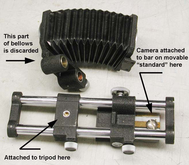
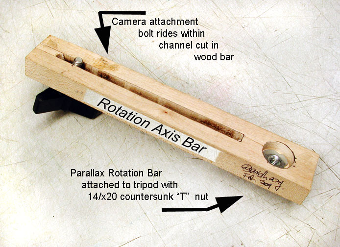
Below you can see an example of the two "varieties". The wooden example is quite straightforward. The 12 inch or so length of 1x2 hardwood has installed at one end a 1/4 x 20 "T" nut fitted in a slight depression (countersunk) in the wood. There is a 1/4 inch wide by about 8 inch long channel cut along the length of the wood bar.
For use the bar is affixed ot the tripod''s head by the "T" nut. The camera is attached to the bar by a 1/4 inch by 20 bolt reaching up from below to tightly hold the camera against the bar at positions such that the lens is located above the "T" nut with the camera attachment bolt at various positions. This allows the camera to rotate about a point typically below the lens rather than at, or below, the camera body.
Determining the proper rotation point for panoramic photography is a matter of trial and error and is described later.
In the case of the metal panoramic rotation bar made out of a discarded bellows device a 1/4 inch hole was drilled in a rack-and-pinion device that was part of the bellows such that the camera could be attached to this movement. Many cheaper bellows do not have this type of capability. In that case one needs to devise a scheme for attaching the camera to one of the "standards" that carry the lens or by which the camera is attached to the bellows.
The bellows device had its own tripod attachment socket and that did not need any modification. For use, the camera body is attached to the rack-and-pinion movement or to the standard that can be moved with respect to the part of the bellows mechanism that attaches to the tripod.
Hopefully the attached illustrations give you an idea of what needs to be done!
For use, in either case, the camera is attached to the "rotation bar" and it in turn is attached to the tripod. You will notice that as the tripod head is turned the camera is also turned but about an axis no longer going through the camera body but about an axis somewhat further forward of the body. Maybe somewhere below the lens at some point.
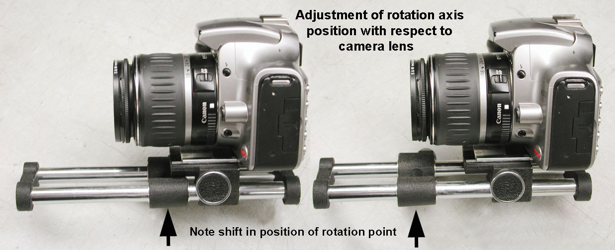
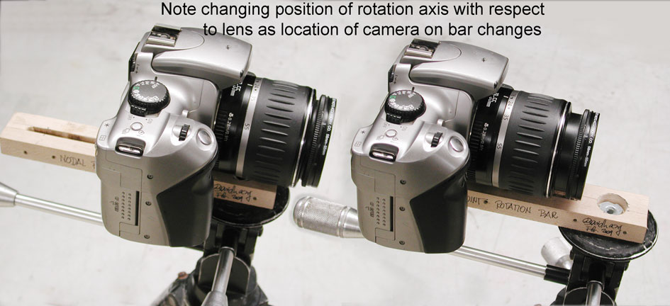
Above you can see the metal carriage salvaged from the vintage bellows unit and below is the hardwood equivalent. Both show how the rotation axis moves below the camera lens as the camera is moved closer or farther away from the rotation axis of the tripod.
Now, for use, the tripod itself first needs to be leveled so that when the head is turned it turns in a horizontal plane and does not wander up/down as it makes a 360 degree turn. A little patience at this time is indicated!
Once the camera is leveled, while looking through the viewfinder, identify a nearby object whose image seems to just touch the edge of a far object while this edge is located in the middle of your camera's viewfinder.
Now turn the camera left and then right making that contact point move from one side of the frame to the other. Notice if the two edges that you chose earlier and which were touching remain in contact as you pan the camera from side to side. If they remain in contact you are all set. But more than likely they will separate or overlap. This means you need to adjust the position of the camera on the rotation bar. Move the camera closer to the tripod's axis of rotation (or farther) and repeat the process of swinging the camera form side to side.
At some position of the camera you will notice the "desirable condition". This is that as you swing the camera the edges of the two subject will remain in contact.
Once you have arrived at this condition the camera is rotating about the center of perspective or entrance pupil of the lens.
Now you can decide on how many photographs you will make to cover whatever angle of the scene you want to record. That process is beyond the scope of this brief article whose purpose was to simply encourage you to make an inexpensive, no frills, panoramic rotation bar.
These rotation axis bars can be used for panoramic photography but they also can be used for other purposes where it is desirable to maintain a fixed relationship between foreground and background objects as the camera is panned from side to side.
If you found this article of interest or if you have questons or comments please feel free to drop me a line at my email address. Andrew Davidhazy, andpph@davidhazy.org