TAILFLASH SYNCHRONIZERS FOR ACTION PHOTOGRAPHYby Andrew Davidhazy
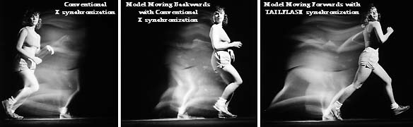
Action photography which combines a blurred image due to a long exposure by tungsten illumination with an action freezing burst of light from an electronic flash is no longer an unusual technique. However, the methods used by photographers to achieve these photographs vary widely. They range from fortuitous accidents to highly predictable images. The cost for the equipment used is sometimes negligible but most of the time the cost in time, materials and equipment is considerable. Most often the images are built-up "in reverse". That is, the flash is flashed first and then the action is acted out by the model "backwards". This is so that the blur will appear to precede the flash, thus indicating the direction from which the motion is coming. This results in images that look very much like cartoons of speeding subjects, where the artist adds "speed lines" to indicate the direction of motion. In cartoons and art these speed lines trail the subject. This effect is rather difficult to achieve photographically because shutters are designed to cause an electronic flash to fire immediately upon (or just before) reaching their fully open state. Therefore, if you were to attempt combined tungsten/flash pictures yourself you'd find that when your shutter is set to a short time exposure or set on B the flash would go off first and the image due to the tungsten light would trail off in the direction that the subject is moving. If the subject is moving normally, then the blur in the picture will appear backwards in relation to artistic convention. That is why photographers generally deal with the production of these images under highly controlled studio situations and ask their models to perform a given motion backwards. Sometimes this is fairly easy to accomplish. With movements which depend on gravity, however, motions can become rather awkward when one attempts to perform them backwards. There are a number of solutions to this problem and often they depend on the kind of a shutter that your camera is equipped with. The most versatile and applicable shutter for the successful production of these flash/blur pictures is the leaf or diaphrag shutter. The larger diameter ones fitted to view cameras are particularly well suited for this process. If you only have a focal plane shutter available it can be made to work too but the process is complicated by the fact that in focal plane shutters the exposure takes place by the sequential uncovering and covering of the film by the moving curtains rather than by the simultaneous exposure of the total film gate which is the case with leaf shutters.
In an attempt to simplify the methods by which a photographer might generate successful images at a lower cost, I devised two methods for generating a TAILFLASH or for setting a flash off AFTER the tungsten exposure. One of these is an electronic method and is designed strictly for use with leaf shutters. The other is mechanical in nature and can be used with leaf and focal plane shutters. Both methods depend on the fact that the trigger circuit of most small flashguns contains a very small capacitor which is discharged into the trigger coil at the instant that the camera synchronization contacts close and the fact that the charging of the trigger capacitor and the main capacitor are for all intents and purposes isolated from each other. After a typical handgun is fired, it starts to recharge its main and trigger capacitors. The trigger capacitor can not recharge, however, until the shutter sync contacts are opened. This is so because while the contacts are closed the trigger capacitor is in fact "short circuited" and the charge that would normally go into it is bled to ground. Since the trigger capacitor is "insulated" from the main capacitor by high resistances and other protective circuits, the fact that the shutter contacts, in effect, short circuit the trigger capacitor does not damage the camera, us or the trigger circuit. Normally we are not aware of the above fact because we usually do not expect a flash to fire again while the shutter is still in the open position. As explained above, a flash is fired when the shutter blades reach their fully open position causing the sync contacts to close. At the end of the exposure the blades start to close again and the sync contacts resume their original open position allowing the trigger capacitor to charge up again. The opening of the sync contacts generally happens while the shutter blades are still 95% to 90% still open. This bit of knowledge along with the fact that most trigger capacitors charge up to a useable value in a fraction of a second is the basis on which the following two triggering methods are designed. Both depend on an "inverting" circuit. That is, one which opens a contact upon another one closing and closes the contact upon the other one opening. The use of an inverter circuit is applicable to the solution of this "tailflash" technique because we would like the flash to go off when the shutter opens its sync contacts rather than when they close. To accomplish this you can modify your shutter ( a rather expensive proposition!), buy a shutter with this feature already buit in ( also expensive ) or improvise a system as suggested below ( quite inexpensive ). Anyway, since the shutter sync contacts are normally in an open state the flash does not fire when it is first plugged into the PC contacts. If you build the circuit suggested below, however, since it's output contacts are normally in the closed position the flash will be fired when first connected to them. After this initial discharge the flash should behave normally and start to recharge its main capacitor. The trigger capacitor on the other hand will continnually be bled to ground through the closed contacts of the inverting circuit or switch. Then, when the camera's shutter is operated the sync contacts close and the inverting circuit's contacts open allowing the trigger capacitor to recharge. This often takes less than 1/4 second. When the exposure is terminated and the sync contacts start to open again, the contacts of the inverting circuit close again causing the trigger capacitor to discharge and the flash to fire before the shutter blades have a chance to move an appreciable distance.
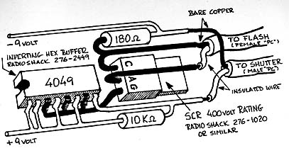
Exposure times of less than 1/4 second may not give the trigger capacitor enough time to fully recharge and thus should be tested with your particular unit. Since the closing shutter blades invariably "cut into" the maximum diaphragm opening of your lens to some extent, smaller than maximum aperture settings are recommended for predictable exposure control. Most small flashguns can be operated this way. I have successfully triggered Vivitar and Sunpack flashes with this synchronizer at exposure times down to 1/15 th second. If you have trouble with a larger unit then I suggest you slave the noncooperating flash to one that can be fired reliably. Here is a later version of the inverting synchronizer scheme built onto a 14 pin IC socket. You may find this circuit easier to build than the one above. A parts list is included and you can see it in greater detail by calling up the larger version linked to the thumbnail image.
The above methods and circuits are only suitable for leaf shutters because in focal plane shutters the camera sync contacts do not open or disconnect until the trailing curtain has completely covered up the film plane. Thus, the image due to the flah exposure falls completely on the trailing shutter curtain rather than on the film. To overcome this problem a simple mechanical inverting switch can be built based on the use of a microswitch which has a Normally Closed contact. Most have it, along with contacts identified as Normally Open and Common. You rig the microswitch up so that an extension from it's feeler arm falls just above the shutter release button of your camera and you adjust the angle of the microswitch so that the feeler arm causes the microswitch to "click" as you start to depress it and to "click" again just before you've let up enough on the camera's shutter release button to terminate the exposure. Therefore, as with the electronic version described earlier, when you first connect your flash to the NC (normally closed) contacts of the microswith your flash will fire (if it was turned on and fully charged). Then, when you are ready to start your exposure you depress on the microswitch feeler arm located directly above the shutter release button. This causes the microswitch to open it's NC contact allowing the flash trigger capacitor to charge and the camera's shutter to open as you continue the downward movement of your finger. When you end the exposure, releasing pressure on the shutter you also allow the microswitch NC contacts to close again thus setting off the flash before your finger has risen to point of releasing the trailing curtain of your camera. This mechanical version can also be adapted to view camera lenses. It's advantages are that malfunctions can generally be identified by simply looking at and listening to the action and that batteries are not required for proper operation. The electronic version has the advantage of ease of use since it merely needs to be plugged into the PC connection of the shutter. In either case, however, it is not so much the device which will yield exciting pictures but the photographer who learns to use it to its full photographic potential. < font face="courier" >
-< Tailflash Synchronizer Circuits >-
4 PART TAILFLASH SYNCHRONIZER FOR LEAF SHUTTER CAMERAS
-9 volt ----------------------------------------------------.
.__________. |
.--------------------------. .____| 180 ohms |__*_____> to shutter
| 16 15 14 13 12 11 10 9 | | |__________|
| | *------------------------> to flash
| IC 4049 | | .-------------.
| | '----| Cathode |
| 1 2 3 4 5 6 7 8 | .----|-------------|-----> to flash
'--|--|--|--|--|--|--|--|--' '----| Anode |
| | | | | | | | | C106D SCR |
| | *--|--*--|--*--|-------------| Gate |
| | | | | |_____________|
| | | | |____________________________*____> to shutter
| | | | .__________. |
+9 volt ___*__*_____*_____*___________________| 10 Kohms |___|
|__________|
Note: On IC 4049 pins 9-16 are not connected to anything. Use a 16 pin IC
socket rather than soldering to IC leads directly.
Note: SCR output is polarized and if flash does not work one way try reversing
connections. SCR must be able to deal with 250 volts or so.
Suggest these SCR's as suitable: CR3CM, 54003LS3, BRY55 (nice, small unit)
Note: * signifies connection
Note: When connecting flash to device it should fire. Wait a while and then
close the connection between the two shutter contacts. Nothing should
happen when you do this. When you disconnect them, however, flash should
fire. Shutter speeds shorter than 1/15 second may not work.
EDGE DETECTOR TYPE TAILFLSH SYNCHRONIZER CIRCUIT FOR LEAF SHUTTERS
............. .............
+9 volt ----| 6.8 Kohm |----*----| 6.8 Kohm |-------------------> to shutter
|___________| | |___________|
| ..............
| | Anode|------------------> to flash
| | Cathode|--------------*---> to flash
._____________________| |C106D SCR | |
| | Gate|----. |
| ............. |____________| | |
*----| 1N4148 | |----. .________| |
| |_________|_| | ........ | |
| ............. | | | | ............. |
:____| 470 Kohm |____*__| .1uF |___*__| 6.8 Kohm |___*
|___________| | | |___________| |
|______| |
0 volt -------------------------------------------------------*----> to shutter
Note: SCR output is polarized and if flash does not work one way try reversing
connections. SCR must be able to deal with 250 volts or so.
Suggest these SCR's as suitable: CR3CM, 54003LS3, BRY55 (nice, small unit)
Note: * signifies connection
Note: Shutter speeds shorter than 1/15 second may not work.
Note: Connect to flash with female PC cord, to camera with male PC cord.
copyright 1993 - andrew davidhazy
non-commercial uses permitted
----- comment below from a reader of the above article:
Date: Thu, 03 Feb 2000 22:15:10 +0800
From: Steve Hodges
|