|
Bad Timing?
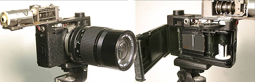
Andrew Davidhazy Imaging and Photographic Technology School of Photographic Arts and Sciences Rochester Institute of Technology (This article was originally published in Industrial Photograpy magazine) Some time ago, I received a request to determine the flashing rate of three strobes placed on a tower near the local airport. I had often noticed these flashing lights, but before receiving this assignment, never paid much attention to them. At first, I didn’tthink much of the request; I assumed that the task could be accomplished by simply watching the lights and using a stopwatch, visually counting the number of flashes which occurred in a given time period. After a more detailed examination of the event, I realized that the three strobes on the tower were not flashing simultaneously. It also seemed that the strobes were not behaving in the same manner. While a simple phone call to the “guardian” of the tower could probably have answered many questions, I was informed that this course of action was not permitted. I also learned that all the strobes were supposed to be flashing simultaneously, and my help was sought because there seemed to be a number of inconsistencies in the lights’ behavior. It was, in fact, suspected that the strobes went off at different times and that some flashed more than once. Therefore, my task was not simply a matter of discovering the flashing rate; instead, I had to find out the exact timing of the flashes within a group of flashes, which appeared to be a single flash. At first glance, it seemed the problem should be tackled with a standard high speed film or video camera. After thinking about the situation, it soon became apparent that this type of equipment would pose several problems: Valuable information could be lost “between” frames or successive flashes could superimpose their images on one another. In either case, the results could lead to misinterpretation and misinformation. A different method was required. I needed a device which would never lose sight of the subject yet would show the subject at various times. A device which performs in this manner is known in technical photographic circles as a streak, camera. Streak cameras are also known as strip cameras; they differ only in the direction in which they photograph a moving subject. A streak camera consists of a camera body fitted with a fixed or variable aperture slit located close to the film plane and some means for transporting the film behind the slit. While almost any 35mm camera can easily be adapted to meet these requirements, a somewhat more dedicated camera was designed and built for this task. Constructing a streak camera To construct this streak camera, I modified a Werlisa 35mm camera with a plastic body (available for a retail price of approximately $15). To modify the Werlisa for this specific task, I first removed the lens cone and shutter assembly. Next, the camera body was fitted with a Leica-type body flange, so that it could be fitted with a Leica threaded lens. While the flange to film distance was not exactly Leica depth, I recalibrated the lens’ distance scale based on images checked for sharpness at various distances using a ground glass inserted in the focal plane. Actually, since the strobes would be photographed from a distance, only the lens’ “infinity” distance was critical. The next step was cutting a 1mm wide slit in a mask, constructed from lithographic film developed to maximum density. This mask was installed in the camera’s focal, or film aperture, gate with the slit positioned so that it would appear in the middle of the frame. Next, I tackled the film transport mechanism. A mechanism to move the film in the camera was salvaged from a discarded Pentax motor drive. Basically, the mechanism consists of a geared right angle drive, powered by a small permanent magnet DC motor. The stripped motor was attached to the camera’s top deck, so that the drive shaft was located directly above the film winding mechanism. The camera’s film advance consists of a large thumb wheel connected to the motor drive with two pins and stiff wire arms shaped like an inverted “V” extending down from the drive’s shaft. As the arms rotate, the pins located on the thumb wheel are engaged, causing the film to advance at the rate of 38mm—one 35mm frame plus inter-frame space—for each revolution of the thumb wheel.The rate at which the film moves is controlled by supplying the motor with voltages ranging from three to 18 volts DC, available from a separate battery pack. Initially, I was able to determine the rate of film movement only by keeping track of the rate at which the motor drive’s shaft was turning. However, I was eventually able to improve upon this, as will be shown later.
With the camera finally assembled, I went up onto our roof one night and aimed the camera at the strobes. Using the ground glass as a guide, I positioned the camera so the strobes would fall along the camera’s slit. Then, I loaded the camera with Tri-X film and tested it at various speeds. After the film was processed, examination of the negatives revealed that a better method of determining the rate of the film movement was necessary. As I reexamined the scene, I noticed that a sodium vapor street lamp appeared in almost the same line of sight as the tower lights. I realized that because this type of light is sensitive to voltage fluctuations, it will respond with brightness changes to the amplitude variations of alternating current. That is, these lights turn on two times for every current cycle, that is, they ‘flash” approximately 120 times per second. After this “flash” of realization, I realigned the streak camera so that the slit would include not only the strobes, but also an image of the street lamp. Once again, I ran the film at various speeds, but this time I didn’t keep track of the motor rotation rate. 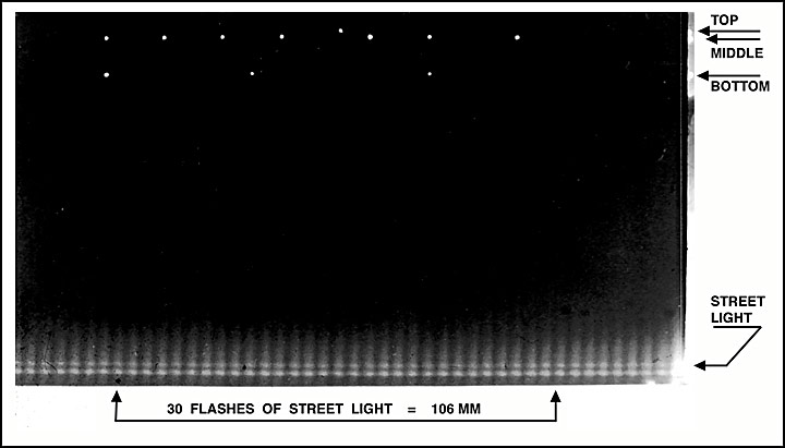 Sample print taken with the streak camera showing dots
corresponding
to the strobe flashes and a regular pattern of dark and light bands
created
by the sodium vapor street lamp. The next step was determining what these images meant in terms of time. By examining an enlargement of a set of marks from the strobes, I was able to discover how much time 1mm of print —in the direction in which the film moved— represented. To do this, I simply measured the distance which 30 flashes of the street lamp occupied (any arbitrary number could have been chosen). Then, I divided this distance by 30/120 second. Through these calculations, I determined that at the enlargement I was working with, the film would have been moving at 424mm per second; therefore, 1mm of paper in a horizontal direction stood for a time of 1/424 second. Next, I measured the “elapsed time” between the marks
created by the
flashing lights. This was accomplished by measuring the horizontal
distance
from mark to mark and multiplying this distance by 1/424, or the time
which
stood for 1mm. After conducting this experiment, I further modified the streak camera by incorporating a substitute for the sodium vapor street lamp, which gave the camera a time base. This attachment, generally referred to as a timing light, produces marks on the film’s edge by using an LED flashing at a known frequency. As a result, I was able to use this terrific timing device without searching for a street lamp to include in the scene Additional applications This streak camera was subsequently used to analyze two other events: The rate at which an opaque dye dispersed into clear water and the length of time it took a motion picture camera shutter to accelerate to a constant framing rate. In both of these examples, the camera’s slit was aimed at
the line in
the subject where changes of interest would occur. The film was set in
motion, while the newly added LED timing light flashed once every 1/10
second to provide a
known time-base to measure changes in the subject. When each event
occurred,
the moving film recorded changes which continuously passed by the
camera’s
slit. Timing the rate of dye
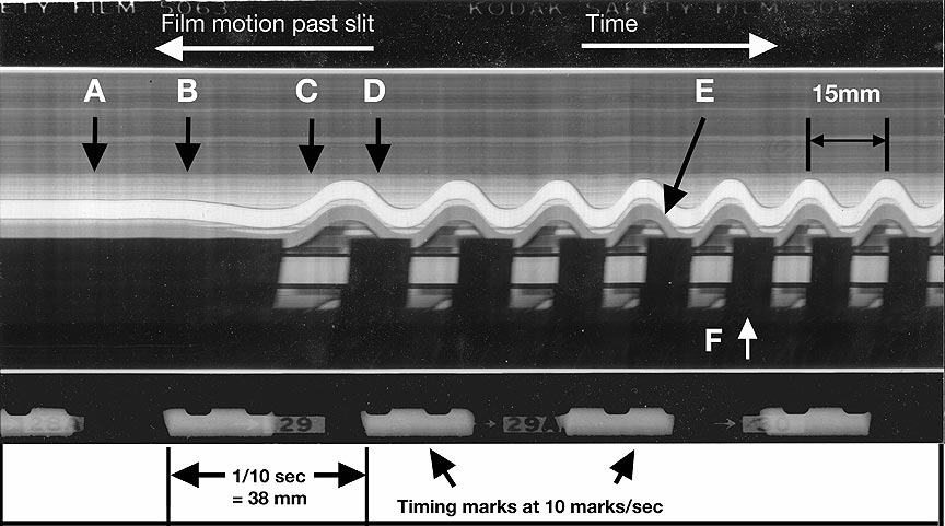
mixing in a glass container 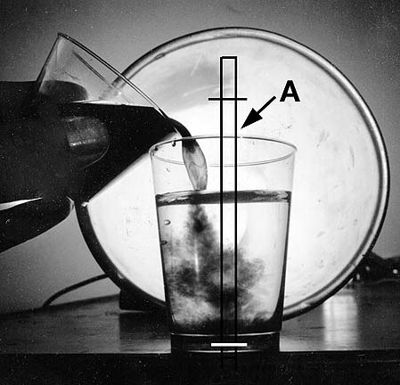 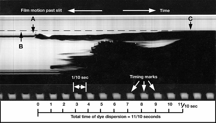 Analyzing the length of time it takes a dye to disperse in a clear host liquid: In the picture on the left the area between the two vertical rules shows the “line” photographed by the streak camera. In the streak picture on the right the sequence of events is as follows: A—Pouring of dye begins. B—Note rise in liquid level of solution as dye is added, C—Container is fully opaque. To calculate the amount of time it took opaque dye to disperse in clear water, an accurate estimate was made by simply counting the number of 1/10 second intervals which elapsed from the time the liquid’s surface was first disturbed until complete opacity. From this photograph, it was determined that it took approximately 1/10 second for the dye to reach the bottom of the glass, but almost one second for it to cause complete darkening of the clear water originally in the glass. Motion Picture camera
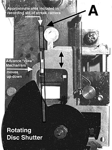
movement FPS and acceleration The frequency of rotation,—and thus the framing rate—of a motion picture camera shutter was measured in a similar manner. In this way, it was easy to visualize the changing rate of rotation of the segmented shutter. The distance between timing marks was constant, indicating that the film was moving at an even rate. In observing the marks on the film representing the camera’s shutter, however, it was possible to see the changes that occur in the distance, and thus the time, between the peaks of its claw advance mechanism’s reciprocating action and the length of each “open” period of the shutter itself before settling down into the pattern associated with a camera running at even speed.
Time for one cycle is l5mm/38mm x 1/10 sec, or .039 sec. The framing rate is the reciprocal of the time per frame and therefore, the camera taking rate is 1 / .039 or 25pps. From this photograph, it was determined that the unloaded
camera shutter
required approximately five rotations to accelerate. Once it began
running
at a steady rate, it did so at 25 pictures per second. Although these studies could also have been performed with a motion picture camera, the data reduction would have been far more complex, and cumbersome graphic illustrations would have been required to help people visualize the process. These problems, partly due to information lost between frames and the great number of separate frames required, are much more easily solved through the use of a streak camera. They say beauty is in the eye of the beholder. When a
bunch of dots
on a black background can be used to solve a complex time sequence
problem,
that’s beautiful!
If you have any questions
or comments about this work feel free to write me at: andpph@rit.edu
|