Photographic Demonstration of Surface and Interior Conditions of an
Unevenly Heated Liquid
Andrew Davidhazy
Rochester Institute of Technology
Distillation Research Laboratory *
Imaging and Photographic Technology
as this appeared in the SPSE Journal, Vol 13, #3, May-June 1969
Note: This was one of the first technical photography papers that I
published. Additional papers can be found in the the SPSE Journal dating from
the very early 70's.
Abstract: Movements of the surface of a liquid and convection currents within
the liquid during heating and cooling are shown simultaneously using a dual
reflection-refraction photographic schlieren system. Means are furnished for
identifying and measuring hills and valleys and correlating these with rising
and descending streams within the liquid. Two models are selected, melted
paraffin wax and isopropyl alcohol, the latter evaporating quietly into its
pure vapor, with air excluded.
Photographs of the movements of the free liquid surface that have been
made during the past 70 years have mostly followed the lead of Henri
Benard (1-3) who photographed convection patterns in and on shallow layers
of melted paraffin wax heated purposefully from below and cooled from
above by natural convection. Methods employed then and later have
comprised chiefly interference and schlieren photography, the latter
occasionally done at oblique angles. Interest has centered more often (4)
on movements within the liquid than on the surface, and the factor common
to nearly all cases is that the liquid has been in contact with air.
This laboratory is concerned chiefly with movements in and on volatile
liquids heated out of contact with air and thus evaporating quietly into
their own unsaturated vapors.* Excluding air permits observation of
evaporation patterns uncomplicated by foreign gas and the later allows one
to watch the effect of gases added to the supernatant vapor. Thermal
convection in an unstirred liquid is maintained by two natural mechanisms,
differences in density within the liquid and differences in tension of the
surface. Heated, buoyant streamers rise, and as they break the surface are
pulled to areas of higher tension that have already cooled, becoming
cooler themselves until they are ready to sink back into the main bulk.
The cumulative effect is to cause departures from the mean level of the
surface amounting to about 10 u for layers 1 cm deep. The deviations were
measured by Benard using interference photography, a method of great
precision and mechanical delicacy, though often the relief patterns are
too large for the working range of the interferometer.
The system of schlieren photography now put forward is less quantitative
but is simple to construct and operate and records convective movements of
the surface or of the liquid beneath or of the two subjects
simultaneously, the camera making a direct vertical approach and thus
securing rectilinear pictures. The method allows the observer to
distinguish hills from valleys on the disturbed surface and thus make
direct identification of rising and descending streams in the companion
pictures.
The optical procedure, sketched in Fig. 1, was developed as an exercise
using the primitive observation cell shown in Fig. 2 and repeating
Benard's classic experiment with melted wax. When the technique had been
mastered it was applied (see Figs. 9 and 10) to the photography of liquids
evaporating out of contact with air.
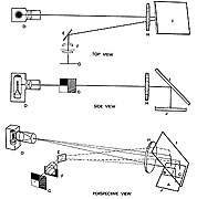 Fig. 1. Three diagrams of an optical system for schlieren photography of
liquid surfaces. In each diagram the light source D projects a beam
through the field lens H to the large mirror I which is positioned at 45
degrees above the liquid surface and slanted slightly sideways. Rays
reflected from the liquid are directed to the small mirror E and thence to
the camera lens which houses the knife edge or diaphragm assembly and come
to a focus on the ground glass G. The lowest perspective view shows an
idealized liquid surface with area A supposedly flat and B and C sloping
towards (+) and away from (-) the camera. One half of the ray-bundle
reflected from A is intercepted by the knife edge at F and the other half
produces a grey image of A on the ground glass. Rays reflected from B miss
the knife edge and form a bright image of B in the camera. Since most or
all of the rays from C are intercepted, a dark image of C appears by
default on the ground glass.
Fig. 1. Three diagrams of an optical system for schlieren photography of
liquid surfaces. In each diagram the light source D projects a beam
through the field lens H to the large mirror I which is positioned at 45
degrees above the liquid surface and slanted slightly sideways. Rays
reflected from the liquid are directed to the small mirror E and thence to
the camera lens which houses the knife edge or diaphragm assembly and come
to a focus on the ground glass G. The lowest perspective view shows an
idealized liquid surface with area A supposedly flat and B and C sloping
towards (+) and away from (-) the camera. One half of the ray-bundle
reflected from A is intercepted by the knife edge at F and the other half
produces a grey image of A on the ground glass. Rays reflected from B miss
the knife edge and form a bright image of B in the camera. Since most or
all of the rays from C are intercepted, a dark image of C appears by
default on the ground glass.
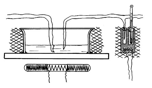
Referring now to Figs. 1 and 2, the upper part of a beaker, 10 cm
diameter, was cemented onto a slab of heat resistant plate glass and
filled to a depth of 5-30 mm with paraffin wax melting at 400C. An annular
heater was mounted beneath the slab and monitored by a wattmeter and
variable transformer. Glass wool batting (cross hatched) and screens (not
shown) protected the assembly from draughts. A thermocouple recorded the
average wax temperature while opposed couples held in vertical alignment
indicated the direction and degree of thermal gradients.
The optical model diagrammed in Fig. 1 consists of a light source, a field
lens of 40 in. focal length and 4 in. diameter, a 5 x 7 in. first surface
mirror, a second smaller mirror, a beam splitter, a knife edge, and a 35 mm
camera equipped with a long focus lens.
Rays from a 1000 watt light source are condensed by a small lens and
directed at the field lens from a distance of about 80 in. or two focal
lengths. The large mirror reflects the light beam from the field lens
vertically down onto the surface under examination. A small amount of the
light incident on the surface is returned to the mirror, carrying
information about surface irregularities in the form of rays which have
deviated from the path they would have taken had the surface been plane.
From the mirror the reflected beam passes in the reverse direction through
the field lens to become focused somewhere near the original light source.
In order to utilize the focused beam without interfering with the source,
the small mirror is placed near the focus to deflect the beam 90~ to one
side to the knife edge and camera.
The camera is moved back and forth until the beam from the field lens is
focused sharply on the lens diaphragm or a knife edge substituted for it.
The camera is then focused accurately on the surface of the liquid and the
beam relocated if necessary onto the diaphragm. The camera is now ready to
be moved up or down so that the knife edge will split the beam in two at
the focal point. This allows half the light to pass above the knife edge
and half to be interrupted.
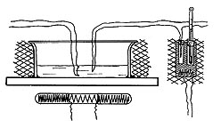 Fig. 2. Half beaker observation cell. Two sets of thermocouples, center,
are positioned against the side of the beaker above the gap in the annular
heating coil. Opposed thermocouples measure the direction and degree of
thermal gradients. The single thermocouple is balanced against a reference
couple maintained at known temperature in the cell to the right and
measures the average wax temperature.
Fig. 2. Half beaker observation cell. Two sets of thermocouples, center,
are positioned against the side of the beaker above the gap in the annular
heating coil. Opposed thermocouples measure the direction and degree of
thermal gradients. The single thermocouple is balanced against a reference
couple maintained at known temperature in the cell to the right and
measures the average wax temperature.
When the liquid presents an absolutely flat surface, becoming a plane
mirror, represented as area A of a formalized surface in Fig. 1, a
uniformly grey image of area A will appear on the focusing screen of the
camera. However, if a bundle of rays is reflected from an uneven surface
so that it strikes below the edge of the knife in the camera lens, it's
absence will appear as a dark spot on the ground glass. Conversely, if it
is bent so that the whole bundle passes the edge, it will appear as a
brighter region than the average grey of the flat area which received only
half a ray -bundle. As with any schlieren system, this one is sensitive to
surface slopes (or refractive index differences) in one direction only.
This is determined by the position of the knife edge. Any displacement of
the light source image in a direction perpendicular to the edge will be
recorded as a gradual lightening or darkening of the ground glass. The
system is not sensitive to horizontal displacements. In the arrangement
described in Fig. 1, the edge is parallel to the optical axis from the
light source to the field lens and it is placed so that it cuts off the
bottom half of the image of the light source. Thus any inclined surface
which has a negative slope, such as area B, which slants away from the
light source, will produce a dark image on the ground glass and an
inclined surface with a positive slope, area C, a bright image.
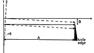 Fig. 3. Geometry for ascertaining surface deviation. The significant
parameters are A, the distance from the surface to the knife edge, and B,
the dimension of the light source normal to the knife edge. It is arranged
that half the beam reflected from the vertical surface 1 passes
beyond the knife edge. All of the beam reflected from surface 2, tipped at
angle 0, is just intercepted. The angle 0 is thus determined by the attainment
of complete interruption.
Fig. 3. Geometry for ascertaining surface deviation. The significant
parameters are A, the distance from the surface to the knife edge, and B,
the dimension of the light source normal to the knife edge. It is arranged
that half the beam reflected from the vertical surface 1 passes
beyond the knife edge. All of the beam reflected from surface 2, tipped at
angle 0, is just intercepted. The angle 0 is thus determined by the attainment
of complete interruption.
The approximate heights of elevations of the surface are calculated from
two parameters, the distance of the field lens from the knife edge (A in
Fig. 3) and the dimension normal to the knife edge of the image of the
light source (B in Fig. 3) as focused onto the knife edge. Then, if the
surface is optically flat, as in position 1, and the knife edge is
positioned to cut off half of the image of the light source, the
brightness of the image of this flat area on the camera screen is
diminished by 50%, that is, acquires a virtual reflectance of r = 0.316.
Where the liquid surface is inclined, e.g., 0 = ± 2 degrees, the image of
the source is shifted with respect to the knife edge and the image of the
surface at the camera is brightened (+) or darkened (-). At those points
on the liquid surface where maximum brightness or complete darkness
(produced by position 2 in Fig. 3) have just been reached, the surface has
attained a maximum slope, which can be calculated. These points are always
less elevated or depressed than the maximum height or depression of
surface deformations.
For instance, let B = 0.4 cm and A = 200 cm, then because A » B
0 in radians 12B 0.2
A 200 0.001
or in degrees = 0 degrees 4'
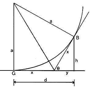
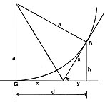 Fig. 4. Trigonometry for calculating surface deviation. The liquid
elevation GB extends d cm from the limits of grey to the limits of black.
E~, the maximum angle of slope, is tangent to the surface at B. Elevation
h above the mean surface is determined from e, Fig. 3, and (x + y) = d.
Fig. 4. Trigonometry for calculating surface deviation. The liquid
elevation GB extends d cm from the limits of grey to the limits of black.
E~, the maximum angle of slope, is tangent to the surface at B. Elevation
h above the mean surface is determined from e, Fig. 3, and (x + y) = d.
To utilize this angle to determine elevations or depressions the
approximation is made that due to surface tension the rate of change of
the surface angle is constant over the distance between flatness and
maximum slope. The surface in Fig. 4 is thus represented by a segment of a
circle, more properly a catenary, but the approximation to a circle is
well within the limits of sensitivities of the method, of radius a. At
point G the image just begins to darken from uniform greyness, ie, from
r=0.316. characteristic of optical flatness, and at point B just reaches
minimum illumination, the image in between becoming progressively darker
from G to B. By trigonometry the height h of point B over point G is
determined from the distance, d, between them, since
d = x+y
x = h / sin O
y = h / tan O
h = d sin O tan O / tan O + sin O
A 1: 1 scale photograph of the surface was measured and d found to be 1.0
± 0.1 cm. Since 0 was calculated as 4', then
h = 1 x 0.001 x0.001 / 0.001 x 0.001 = 1 / 2000 = 0.0005 cm
 Fig. 5. Image juxtaposition by semisilvered rhomboidal prism. Raybundles
from the interior of the liquid and from the surface enter appropriate
face of the prism and are reflected along a common axis to the camera
lens.
Fig. 5. Image juxtaposition by semisilvered rhomboidal prism. Raybundles
from the interior of the liquid and from the surface enter appropriate
face of the prism and are reflected along a common axis to the camera
lens.
Thus the system is capable of resolving an elevation of 5 microns over 1
cm of surface if the slope at one end reaches or exceeds 4'. Once the
slope of a hill is over 4' the sensitivity of the particular setup has
been exceeded and measurements can be made only by increasing the size of
the light source or shortening the distance between the field lens and the
knife edge. On the other hand, slopes and elevations of smaller magnitude
can be detected. In our photographs most changes from grey to black take
place in distances of less than 1 cm. If an area does not reach blackness
in 1 cm we can assume it has a lower slope and lower height than an area
which in 1 cm does reach blackness. Finally, the system's sensitivity can
be increased proportionally by increasing the focal length of the field
lens or decreasing the size of the light source. Usually the limiting
factor is not the optics but background noise, namely the residual
vibration which in spite of elaborate precautions continues to shake the
liquid surface.
The above description applies to the light that is reflected from the
liquid surface. About 95% of the incident beam proceeds through the
density gradients in the liquid and on to the glass-air interface at the
bottom of the vessel where again a minor fraction is reflected. The
reflected portion retraverses the disturbances in the liquid and is
finally focused at a point near the focus of the beam reflected from the
liquid surface.
If the supporting plate is exactly parallel to the free surface, and the
large mirror is positioned at an angle of exactly 45 degrees to the surface, an
observer intercepting the reflected rays will perceive all surfaces and
phenomena superimposed. If the base plate is tilted slightly, the
observer, by shifting eye or camera, may view the top surface or the bulk
liquid layer at will without mutual interference. To place the two views
side by side for simultaneous photography of the surface and liquid
interior, a rhomboidal prism with a beam splitter at one end is used to
deviate the rays reflected from the glass slab to a focus on the knife
edge in a fashion similar to the procedure described for the rays
reflected from the free surface. There is no specific requirement as to
the direction in which the base plate needs to be tilted to separate the
two views; however, we have tilted it so that the image of the liquid
surface is just to one side of the image of the interior, see Fig. 5. This
has been done for Fig. 6 which shows top and internal views of the melted
wax. (A motion picture which illustrates the experiment is available for
loan).
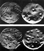
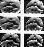 Fig. 6. (left) Simultaneous photograph through melted wax, left, and of
surface, right. Areas on right which are bright to their north are raised
above median level. The lower pair were photographed a half
minute after the upper.
Fig. 6. (left) Simultaneous photograph through melted wax, left, and of
surface, right. Areas on right which are bright to their north are raised
above median level. The lower pair were photographed a half
minute after the upper.
Fig. 7. (right) Cooling sequence of melted paraffin wax. Series begins
upper left and ends lower right. Crystallization occurs along markings
which are dark to north, bright to south, identifying them as troughs of
cooler material.
Without further reference to the optical geometry, it may be stated that
the right-hand picture presents a view as though illuminated from the top
of the picture. Where a displacement shows bright on the upper side, then
the displacement may be identified as a hill, or a ridge. Where the
lighter side is below, one recognizes a hollow or a plunge line. Now, the
details in the left band picture are due to changes in refraction caused
by changes in temperature and density of local streamers. Since reflection
features in the right hand picture are directly above refraction features
in the left one, it follows that features identified as hills in the right
hand picture have up-streamers beneath them in the left, while depressions
have down-streamers or plunge lines.
It can also be inferred that during thermal, buoyancy-driven convection,
hills and sometimes ridges are hotter than the average surface temperature
while hollows, whirlpools, and plunge lines are cooler. A verification of
this diagnosis is furnished rather strikingly by allowing the wax to
solidify and remelt during motion picture photography - crystalline
solidification occurs in the regions previously identified as cooler; the
transitions are shown in Fig. 7.
Photography of volatile liquids out of contact with air requires a more
complicated container.
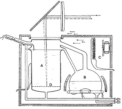
The apparatus seen in Fig. 8 relies heavily on the technique used for
boule-making.(5,6) A new feature, 7 the annular bulge in the center of the
4 in. cylindrical Pyrex container, is to damp standing waves on the liquid
surface. A modified 2-liter flask serves as an evaporator which provides
enough vapor to blanket the test liquid without ebullition. To prevent the
heated air which streams above the observation window in the thermostat
box from superimposing a schlieren pattern on the surface pattern being
photographed, a fan was placed some distance from the box. This entailed
placing another fan inside the box to keep the window warm enough to
prevent condensation on the top of the test vessel. At present the flat
bottom is not in place since the liquid layer required for this section of
our studies is too deep for photography throughout the mass.
 Fig. 8. Apparatus for photography of liquids in absence of air.
Observation cell A is fed with vapor from boiler B. Casing is kept hot by
heater and fan C. Note, expansion in upper walls of A for damping
externally acquired vibrations.
Fig. 8. Apparatus for photography of liquids in absence of air.
Observation cell A is fed with vapor from boiler B. Casing is kept hot by
heater and fan C. Note, expansion in upper walls of A for damping
externally acquired vibrations.
The apparatus was put through its test paces using isopropyl alcohol.
Surface pictures obtained during heating with stepwise increasing degrees
of superheat are shown in Fig. 9 and pictures taken during cooling,
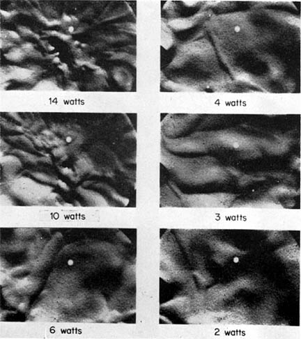
labeled for equivalent temperatures, occupy Fig. 10. It will be noticed
that during the heating period the surface pattern is determined preset)
by the striae of hot liquid which ascend around the walls of the
container. After streaming across the surface, cooling the while, they
form whirlpools generally in pairs which carry the exhausted liquid down
into the general bulk. During the cooling cycle, the surface abandons this
pattern, showing a strong preference for plunge lines but retaining an
occasional whirlpool at the end of a line. The plunge line thus does not
descend vertically but flows diagonally toward the vortex end, as though
each molecule "thought" it could get down faster there. We may conclude,
provisionally, with Spangenberg and Rowland, 8 that a deep liquid finds it
easier to bury its heavier portions in long independent lines rather than
in shorter lines linked into the squares or hexagons that it forms when
convecting in shallow layers. In deep liquids the vortex is adopted only
under externally applied force though this force may itself be exerted by
a plunge line.
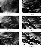
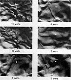 Fig. 9. (left) Surface movements of isopropyl alcohol evaporating in aparatus
of Fig. 8. Wattage input increases throughout the series.
Fig. 9. (left) Surface movements of isopropyl alcohol evaporating in aparatus
of Fig. 8. Wattage input increases throughout the series.
Fig. 10. (right) Surface of isopropyl alcohol cooling from highest degree of superheat of Fig. 9. Heater-induced patterns change to the natural plunge lines of a spontaneously cooling liquid, with the passage of time.
Acknowledgment
The operational techniques other than photographic have been made
available to me from the laboratory. I thank Dr. K. Hickman for direction
and assistance in preparing this paper.
* This work was performed under grant from the Office of Saline Water, U.S.
Department of the Interior. Received November 4, 1968; Revised March 4, 1969.
REFERENCES:
1. H. Benard, Ann. cAirn. PAys., (7) 23, 62(1901).
2. H. Benard, compt. Rend., 134, 260(1912).
3. H. Benard, Rull. Soc. Franc. I’hys., 266, 1125(1928).
4. John C. Berg, Acrivos, Andreas, and Boudart, Michel, "Evaporative Convection," Ads,
in Chem. Pag., 6, 61(1966).
5. K. Hickman, md. Eng. them., 56, 18—31(1964).
6. K. Hickman, J. R. Maa, A. Davidhazy, and 0. Mady, Ind. Eng. Chem., 59, 19-41
(1967).
7. See K. Hickman in OSW Research and Development Progress Report. 1969, now in
preparation.
8. W. G. Spangenberg and w. R. Rowland, ‘Convective Circulation in water Induced by
Evaporative Cooling," Phys. of Fluids, 4, 743-750 (June, 1961).
Copyright, 1969, by the Society of Photographic Scientists and Engineers, Inc.
You can write to the author at: andpph@rit.edu
This page has been visited
 times since
October 15, 2000
times since
October 15, 2000
The counter read 1 on October 15, 2000


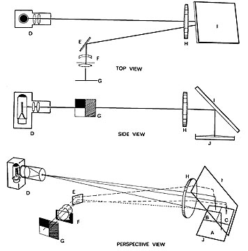 Fig. 1. Three diagrams of an optical system for schlieren photography of
liquid surfaces. In each diagram the light source D projects a beam
through the field lens H to the large mirror I which is positioned at 45
degrees above the liquid surface and slanted slightly sideways. Rays
reflected from the liquid are directed to the small mirror E and thence to
the camera lens which houses the knife edge or diaphragm assembly and come
to a focus on the ground glass G. The lowest perspective view shows an
idealized liquid surface with area A supposedly flat and B and C sloping
towards (+) and away from (-) the camera. One half of the ray-bundle
reflected from A is intercepted by the knife edge at F and the other half
produces a grey image of A on the ground glass. Rays reflected from B miss
the knife edge and form a bright image of B in the camera. Since most or
all of the rays from C are intercepted, a dark image of C appears by
default on the ground glass.
Fig. 1. Three diagrams of an optical system for schlieren photography of
liquid surfaces. In each diagram the light source D projects a beam
through the field lens H to the large mirror I which is positioned at 45
degrees above the liquid surface and slanted slightly sideways. Rays
reflected from the liquid are directed to the small mirror E and thence to
the camera lens which houses the knife edge or diaphragm assembly and come
to a focus on the ground glass G. The lowest perspective view shows an
idealized liquid surface with area A supposedly flat and B and C sloping
towards (+) and away from (-) the camera. One half of the ray-bundle
reflected from A is intercepted by the knife edge at F and the other half
produces a grey image of A on the ground glass. Rays reflected from B miss
the knife edge and form a bright image of B in the camera. Since most or
all of the rays from C are intercepted, a dark image of C appears by
default on the ground glass.