|
Reflection schlieren photography of
liquid surfaces
To begin with, as in any schlieren system, the light
source is a small source such as provided by a lamp with a small,
compact, straight, linear filament. Often tail lamps designed for
automotive use are quite suitable for this purpose.Andrew Davidhazy Imaging and Photographic Technology School of Photo Arts and Sciences / RIT Schlieren imaging is widely used to visualize and study convection patterns in gases due to density differences or gradients cause by thermal effects and for study of shock waves and similar phenomena caused by pressure effects caused by compression or expansion of gaseous subjects. Schlieren is not as widely used to study surface flatness of subjects such as liquids or gases although a "knife edge" test is sometimes used to determine the curvature or "figure" of a mirror intended for astronomical purposes. To study surface flatness a reflection based schlieren system can be set up roughly following the arrangement associated with a single mirror schlieren setup used for the visualization of density gradients. 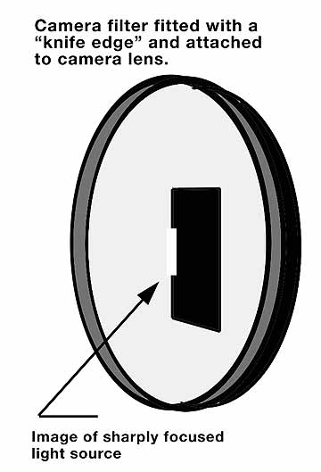 The second item required for setting up
a
schlieren system is a stop or
knife edge. This need be nothing more than an opaque edge made of metal
or some other material. It can also be a transparent obstruction such
as a filter array, as illustrated below, where a narrow central filter
is flaked by larger
filters of a different color such as shown in the illustration. The
knife edge can be located in an independent mount or attached to the
lens shade or filter thread of a camera lens. In fact, a clear or UV
filter for the lens can be the "carrier" of the edge which can be a
blackened razor blade or a piece of opaque film, plastic, or similar
material. The second item required for setting up
a
schlieren system is a stop or
knife edge. This need be nothing more than an opaque edge made of metal
or some other material. It can also be a transparent obstruction such
as a filter array, as illustrated below, where a narrow central filter
is flaked by larger
filters of a different color such as shown in the illustration. The
knife edge can be located in an independent mount or attached to the
lens shade or filter thread of a camera lens. In fact, a clear or UV
filter for the lens can be the "carrier" of the edge which can be a
blackened razor blade or a piece of opaque film, plastic, or similar
material. Third, a schlieren "field" lens is required. This lens determines the practical size of the largest object or area that can be photographed. It helps if the lens is an achromat. Since a schlieren system depends on the interaction of a sharply focused moving image of the light source against the stationary "knife edge" it is desirable that all wavelengths come ot a common focus. This is possible with mirrors but highly unlikely when using lenses. Even if an achromatic lens is used. Such a lens brings some light rays to a common focus but not all. Even with a highly corrected achromat (read expensive) typically these two points of sharp focus are at either side of green. Fourth, if one is to study liquid surfaces, a first surface mirror of a size roughly equal in width to the diameter of the field mirror and about twice that diameter in the length dimension. This can be an oval shaped mirror or a rectangular one as might be available. Finally a camera with a lens of focal length such that the field lens's image is as large as desired at the image plane of the camera is also needed if one is to make a permanent record of the appearance of the subject being visualized by the system. The components listed above are arranged as shown in the illustration below. 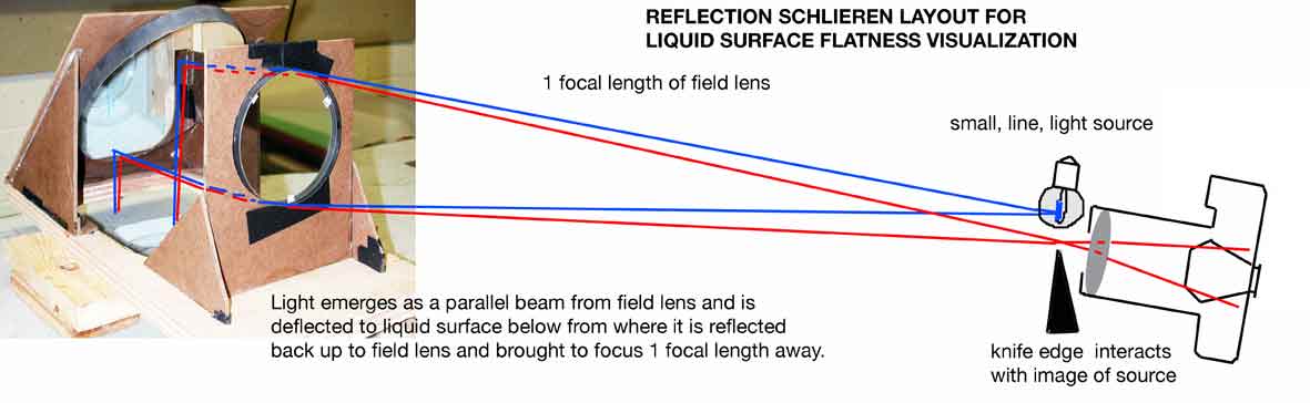 The field lens is set up at some location and the light source is adjusted so that it is located exactly one focal length of the field lens away from it. This location can be readily found by examining the light rays leaving he lens. Placing a white screen on the other side of the lens should produce a circle of light that remains the same diameter regardless of how far away the screen s placed away from the lens/ This indicates that then is focusing the light rays at a point referred to as infinity. The light rays leaving the lens are for all intents and purposes parallel. That parallel bean of light exiting the field lens is not intercepted by the first surface mirror angled at about 45 degrees so that it deflects the beam downwards towards the location of the surface to be examined. When the a small portion of the light rays falling on the liquid surface are reflected from the surface they travel upwards towards the first surface mirror and from there they are redirected through the field lens and are brought to a focus close to the location of the light source. They would fall exactly where the light source is located if the mirror were exactly of 45 degrees but since it is not the light source and its image will be slightly displaced from each other. The knife edge is placed at the focus of the image of the light source in such a manner that about 1/2 or somewhat more of its image is cut-off by the edge. 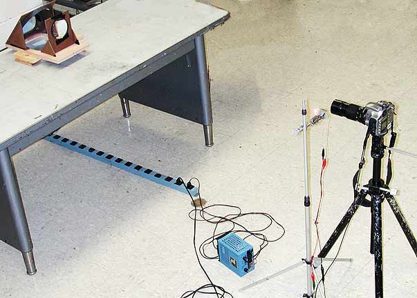 The camera lens is placed beyond the knife edge and if properly aligned the screen of the camera will show a brightly illuminated circle corresponding to the image of the field lens when the knife edge does not cut into the image of the light source. The knife edge may be oriented horizontally or vertically. In the example below it is oriented vertically and the system then responds to changes in the position of the image of the knife edge that cause it to move at right angles to the edge or in a horizontal direction. 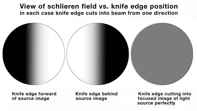 When the knife edge is moved into the image of the source the field or surface of the image of the field lens will darken uniformly or mostly so. Very small changes in the position of the knife edge towards or away from the field lens will cause the darkening of the image o f the lens to change from one side to the other. This is caused by the knife edge intercepting the light rays either too close to the mirror or too far away. When located exactly at the focus of the field lens the image of the surface of the field lens will appear to darken uniformly or mostly so. The field may appear slightly colored instead of uniformly gray due to chromatic "aberration" of the field lens. 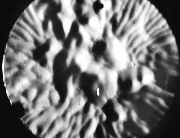 The above assumes that the light rays
reflected back to
the camera lens
from the surface from which they are reflected
are all parallel to each other. This can only be the case if the
surface is flat. If there are regions of
the surface that are not flat they will reflect light back in a
different direction than those reflected from flat areas of the subject
and those rays will either be intercepted by the knife edge leading to
a subtraction of light from those areas at the subject or if the
surface is inclined in the opposite direction then those light rays
will move the image forming ray associated with those areas in an
opposite direction and those areas will increase in brightness. This is
shown in the visual example of the appearance of a non-flat
surface of a layer of convecting liquid The above assumes that the light rays
reflected back to
the camera lens
from the surface from which they are reflected
are all parallel to each other. This can only be the case if the
surface is flat. If there are regions of
the surface that are not flat they will reflect light back in a
different direction than those reflected from flat areas of the subject
and those rays will either be intercepted by the knife edge leading to
a subtraction of light from those areas at the subject or if the
surface is inclined in the opposite direction then those light rays
will move the image forming ray associated with those areas in an
opposite direction and those areas will increase in brightness. This is
shown in the visual example of the appearance of a non-flat
surface of a layer of convecting liquid In practice it is recommended to use a fairly simple camera lens and to set the system up use the lens stopped down to a small aperture. This will ensure proper alignment of the camera with respect to the incoming light beam. Watch out for the diaphragm blades cutting into the expanding light beam beyond the focused image of the light source as this will lead to vignetting of the field. Once the system is set up and aligned with the lens stopped down the aperture can be opened up somewhat for actual photography. 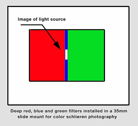 Reflection schlieren is generally a very sensitive
system
and surface
vibrations induced by very slight tremors in the environment can be
readily detected, visualized and recorded. Further, slight surface
relief alterations caused by convection under the surface that cause
the surface to acquire some "topography" can also be detected as shown
in the B&W record above. Reflection schlieren is generally a very sensitive
system
and surface
vibrations induced by very slight tremors in the environment can be
readily detected, visualized and recorded. Further, slight surface
relief alterations caused by convection under the surface that cause
the surface to acquire some "topography" can also be detected as shown
in the B&W record above.Both of these effects are shown in the illustrations below. In these photographs the solid opaque knife edge was replaced with a transparent filter array that performed the function of the opaque knife edge but which instead of stopping light it merely colored it depending on the degree to which the image of the light source was deflected from the narrow central filter. In this case that filter was a blue one flanked by red and green filters. 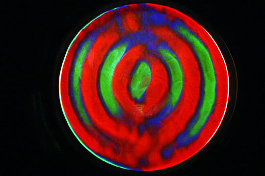 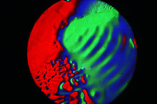 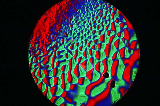 At left there is a strong vibration pattern apparent in the subject while the record on the right shows surface irregularities caused by the liquid surface becoming very thin and developing a pattern of cells associated with that condition. In the middle record both surface evaporation effects and vibration induced effects are visible. If you have questions or comments about the material in this article feel free to drop me a line. Andrew Davidhazy, andpph@rit.edu
|