|
Simple Light Slave Synchronizers Andrew Davidhazy
The subject of setting off a flash in response to the light of another one is a problem that comes up from time to time in photographic situations. There are various commercial solutions available to the photographer. "Slave" triggers are abundant in the marketplace and their price is generally quite affordable for photographers to have several of them in their inventory of equipment. However, from time to time it still happens that one might not want to invest in a slave synchronizer or that one needs one at a time when supply stores are closed or one simply wants to make one's own instead of buying a ready-made one simply for the challenge of constructing it oneself. Here are a couple of circuits that should get you started. I am assuming that rigorous explanations of electronics theory will not be required and I am taking a more "folksy" and approximate description than a technically 100% correct one. These circuits come with no guarantee that they will work since you may be assembling differently than I did and you may be using parts other than those I used. At the heart of any synchronizer is an electronic (or mechanical) switch. It is this switch that causes a flash that is connected to it to fire when the switch closes. This switch makes a connection to the flash by way of the "PC" connector built-into most camera bodies. In a slave synchronizer the switch is typically an electronic one. There are various types of electronic switches that are used but one that I have found to be quite reliable and inexpensive is the BRY55 400 volt device which is an SCR. We don't need to know exactly what an SCR is other than the fact it is a switch and it must be connected properly to a flash for it to work as desired. Many electronics part supply stores carry this device or can order it. Otherwise it is also available by mail order. It should cost no more than $1 or so. The BRY55 SCR has three interface connections or wires leading out of it to external control devices. One of these is the A or Anode or the + side, another is the C or cathode or the - side and the third is the G or gate. The SCR can be activated by a small electrical current applied to its G or gate connection with respect to its C or cathode connection. To generate the small current that is required to make the SCR to activate, conduct or "fire" one needs to find a device or system for changing light into electricity. In the examples given the process starts with a light sensitive device that detects the light from the first or main flash. In the first circuit shown here a small solar cell does this effectively. The signal generated by the cell is then amplified by a transformer and the output of the transformer is connected directly to the input connections of the SCR, namely the C and G leads. The transformer is a small audio transformer. It has five connections. Two of them are associated with a low resistance and the other three with a higher resistance with a center "tap" (which we will not use). One of the connections on the "low" side is connected to one on the high side and this connection is also connected to the minus side of the solar cell and also to the G connection of the SCR. The other connection on the low side goes to the + side of the photocell while the other high connection of the transformer goes directly to the C connection of the BRY55.
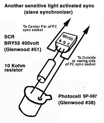
The active parts of the circuit are now complete and it remains to connect a female PC connector salvaged or cut-off from a flash PC-to-PC extension cord. These are cords, often coiled cords, that have a female PC connector on one side and a male PC connector on the other. They allow for extending the distance form a flash to a camera (for example) beyond the reach of standard-length flash synchronization cords. You cut the female end off the extension cord and connect it to the sync circuit as follows. Identify which of the two wires in the PC cable goes to the center hole of the PC connection. That is the one you want to connect to the A lead on the BRY55. The other wire in the PC cable then gets connected to the C connection on the BRY55. If you now plug a flash's sync cord's male PC connector into the female socket of the light slave circuit you just built, firing a flash in the vicinity of the synchronizer should make the flash connected of the synchronizer fire as well. The second slave circuit is a bit simpler but it depends on being able to obtain not only the BRY55 but also another light activated device such as a SP-597 (or equivalent) photocell. It has two wires leading out from it. The one next to a tab on the edge of the device gets connected to the C connection on the BRY55 and the other one first has attached to it a 10Kohm resistor and this is connected to the G connection on the BRY55. The rest of the assembly related to attaching the female PC socket to the light slave is the same as described already. In the drawing above the "Glenwood" reference is to a local electrical supply house. Either of the devices should fire a second electronic flash connected to it in response to another, main, flash. If they don't then try reversing the connections of the PC socket cable to the BRY55 as some flash cords are reversed in orientation. The BRY55 is a polarized device, meaning + has to go to + and to or it fails. I hope that these devices work for you. We have been assembling them in my photo-instrumentation and special effects classes and while I can't say that every student's completed circuit worked first time I was able to trouble shoot all of them and then every one worked as expected! P.S. Possible substitutes for the BRY55 400 "switch" include SCR type
2N5064, Teccor's type EC103B and NTE 5404,
available from sources like Mouser Electronics, and Digikey, among others.
|