|
Andrew Davidhazy
High speed photography is a specialty within the broad discipline of scientific photography associated with making visible and making possible quantitative evaluations of events that transpire over periods of time much too short for visual perception even when aided by the processes of image recording associated with normal photographic cameras. The time frame of certain events can be so short that sometimes neither qualitative nor, more importantly, quantitative evaluation of an event is possible using conventional photographic techniques. When the lifetime of events of interest is of very short duration both higher shutter speeds and framing rates than are normally available on standard cameras are required. When such events happen under adverse and hostile environments this calls additionally for photographic systems ruggedized for such conditions. In addition, when the motion of subjects over time is of interest or there is a desire to record subjects that are too small for the unaided eye to fully appreciate this also calls for special camera equipment. High speed still photography Since it is a relatively simple task to record blurry and unsharp images of almost any event, when photography of fast moving events is contemplated one of the first questions that needs to be answered is whether a given subject will appear sharp and with adequate detail in the final photographs. The answer to this question plays an important role in subsequent decisions associated with the selection of photographic equipment and techniques to achieve the desired result. A basic fact is that any image of an object in motion relative to the photosensitive surface that will record it will, in principle, be invariably blurred regardless of how short the exposure time is that is used to capture the event. In practice one controls blur to fall below some desired threshold value. The factor primarily responsible for achieving perceptibly blur-free reproduction of subjects in motion is the shutter speed or exposure time used for making the original photograph. In simplified terms the shorter the exposure time the less distance a subject can move during the recording phase and the sharper and more detailed an image will be. The actual perception of unsharpness or of the blur in a photograph is largely a function of the observer that evaluates the final image and the conditions under which the observer functions. Visual acuity, angle of view, orientation of the subject, viewing distance, lighting level, color of image, etc. all affect the ultimate perception of sharpness of images. The perceived amount of blur in a reproduction changes depending on the optical magnification that was used when the image was recorded in the first place as well as by the magnification of that image introduced when it is made into a final print. A photograph exhibiting obvious blur can be reduced in size to make the blur imperceptible to the viewer but at the same time the subject's image size is reduced. An image that is not captured with the proper amount of detail (equated here with sharpness) to begin with will show that no improvement in sharpness is possible by altering viewing distance, enlargement, use of alternative focal length lenses, or making changes in camera to subject distance. The exposure time necessary to limit blur in a subject moving at a particular rate can be estimated from the following relationship:
Maximum Allowable Blur (at subject)
where ET = is the exposure time
The Maximum Allowable Blur is often taken as a percentage of subject size. Typically this is about 10% of subject size. This means that one must accurately predict what the smallest part of a given subject one desires detail in is. This then becomes the real subject of the photograph and 10% of which will be assigned the "maximum allowable blur" factor in the above equation. The major problem associated with the making of high speed still pictures of high speed events is achieving short exposure times. Conventional mechanical shutters can reach times as short as 1/10,000 second but this might not be short enough. Good light transmission characteristics and short exposure times are characteristics that are usually not simultaneously available in most shutters. When the action stopping ability of a mechanical shutter is not sufficient to achieve blur-free images, short duration flash illumination sources, either spark or electronic flashes and with durations ranging from milliseconds to less than a microsecond, are traditionally used to achieve desired results. Short duration laser pulses are more frequently used today. There are also special pyrotechnic lighting units available. Fox-Talbot is credited with having made the first high speed photograph in 1840. He placed a page from the London Times on a rapidly spinning wheel. With the light flashes generated with Leyden jars he used an open shutter on the camera and captured easily readable images of the otherwise blurry event. An electronic flash (sometimes also referred to as a "strobe") is a device that stores electrical energy in capacitors over an extended period of time and then discharges it in a brief period of time through a tube most often filled with Xenon or in the case of spark illumination sources by a simple discharge over an air gap. Electronic flashes are often characterized in terms of light output by their watt-second rating, their lighting efficiency and also by their duration. The watt-second rating is determined by the operating voltage of the flash circuit and the capacitance of the main capacitors.
Capacitance x Voltage2
Raising the voltage is a very efficient way of increasing the power level because it is a factor that raises the power exponentially while capacitance increases raise the power arithmetically. A simple watt-second rating of electronic flashes does not completely account for the photographic efficiency of a given flash since it does not take into account the reflector that typically surrounds a flash tube. A better comparison of the photographic effectiveness of electronic flashes is a comparison based on their Beam Candle Power Seconds (BCPS) rating or their effective guide numbers when used with the same film under similar conditions. The duration of a given flash unit can be approximately determined by taking into account the resistance of the circuit while the discharge is taking place plus the capacitance of the main capacitors.
Capacitance (Farads) x Resistance (ohms)
Since it is impractical to raise the voltage beyond certain safe-to-handle limits further gains in power must be achieved by increasing capacitance. On the other hand, since it is not possible to drop circuit resistance below certain limits, achieving short exposure times must be done by dropping the capacitance of the main capacitors. Thus high power and short duration can not be achieved simultaneously and are a matter of compromise in any given flash design. Electronic flash tubes can be disconnected with suitable solid state switches (thyristors in a fairly straightforward R/C circuit) from the power capacitors so that only a fraction of the power available in the capacitors is used at any given time. This increases the life of batteries used to power portable units and also shortens the duration of a given flash discharge while also providing less light. When action stopping capability is required the fractional power settings of many common flash units provide an effective means to achieve relatively short durations suitable for many high speed applications.
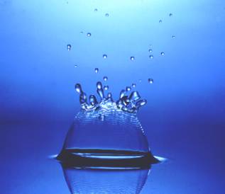
Figure 1. High speed photograph of water drop impact. Flash triggered after a short delay from the time the drop passed through a light beam. Non-conventional High speed shutters Kerr cells and Pockels cells are sometimes used when the goal is to achieve very short exposure times. The former is a liquid medium that aligns the plane of polarization of light in one particular direction. It consists of a glass cell holding the active ingredient (nitrobenzene) which is placed between two polarizers and lined up so that their axes of polarization are at right angles to each other. Therefore no light passes through the system. However, when two electrodes placed in the liquid are energized they cause the plane of polarization of the incident beam to rotate and match the plane of polarization of the second polarizer. This allows light to pass through the system until the electrodes are disconnected. Exposure times in the nanosecond range are possible with such shutters. But, there is a matter of light efficiency. They are not very good in this respect and such shuttering is suitable for events that are highly luminous or where lots of light can be provided but otherwise they are a somewhat impractical for general purpose high speed applications. They are used primarily in weapons and nuclear research applications. A Pockels cell is similar to the Kerr cell except that the active material is a solid instead of a liquid. Another similar shutter is the Faraday shutter that responds to the presence of an electrically induced magnetic field. Since there is always a small amount of light that leaks through the crossed polarizers as used in all of these shutters, generally a second, mechanical, capping shutter is used to exclude light from the camera interior previous to and after the event is photographed. Synchronization Not only is a short duration exposure time needed to make high speed still photographs, one also needs to make sure the photograph is taken at the right time. For this purpose synchronizers are used to trigger either the camera or a light source and sometimes both from a control device that detects some signal associated with the imminent high speed event of interest. Synchronizers are available that respond to just about any kind of an input signal or event but the more popular types include those that respond to a light being turned off or a beam interrupted, a light being turned on, or the onset of sound, or changes in pressure, strain, temperature or motion. Synchronizers typically activate an adjustable delay so that photography takes place at some predetermined time interval after the detection of the synchronization signal. Some can control the sequence of an experiment themselves with built-in circuitry.
Figure 2. Microsecond duration flash photograph with flash triggered by acoustic synchronizer.
Repetitive flash or Stroboscopic Photography. An often neglected form of motion analysis is the application of stroboscopes, (developed to a high level of sophistication by Dr. Harold Edgerton) to the study and visualization of high speed events. If these events are repetitive in nature, a stroboscope often is a low cost instrument that enables the researcher to gather significant data without having to make permanent records of the subject at all. And if records are needed, the instruments can also be used for that purpose in conjunction with cameras in a variety of ways. A stroboscope can be either mechanical or electronic. The latter is usually used for event visualization but there is a lot to be said for the mechanical variety as well. While the mechanical stroboscope is generally nothing more than a rotating disc with one or more "slots" cut into the disc at regular intervals, the electronic stroboscope is essentially a short duration electronic flash that has a very fast recycling time allowing it to be triggered at variable and calibrated time intervals. When the time period of a repeatable event is the same as that of the time between light flashes of the stroboscope the event seems to appear motionless if the ambient light level is low in comparison to the light produced by the flash. Since in such a case our eyes can only see by the light of the flash, and the flash of light (usually lasting only microseconds) happens when the subject is, within each subject cycle, in the same position, the illusion is that the event, such as a rapidly rotating fan, is stationary. The event could, however, make more than one cycle between light flash periods. To determine the frequency of any cyclic event all that is needed are two consecutive frequency "readings" (made off the stroboscope's frequency dial) where the event appears to be standing still. The event frequency (EF) can then be found from:
Frequency1 x Frequency 2
Slip-sync method for studying high speed repetitive events Photographs that can give insight into the motion characteristics of a moving subject can be recorded onto a frame of film by having the subject, illuminated by the flashing stroboscope, perform its motion against a dark background while the shutter of the camera is open for a brief period of time. Those parts of the subject that are in different locations at the time of each light flash are recorded on different locations on the film. By knowing the frequency of the strobe and (by incorporating a scale in the scene) the distance a subject moved between flashes or exposures, the average rate of motion from one point to another can be relatively easily determined.
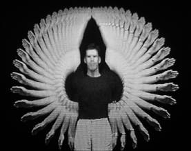
Figure 3. Stroboscopic photograph (at 60 records per second) of human motion made with a Colorado Video freeze frame interface.
Figure 3. Stroboscopic photograph of human motion made onto moving film. Unfortunately, stationary parts of a subject overexpose the film in their locations. Also, if a subject part returns to a previous location it may be difficult to determine the actual sequence of the sequential images recorded by the film. To deal with this eventuality stroboscopes are sometimes coupled with cameras that are simply shutter-less film transport mechanisms. They generally either simply transport film from a supply roll onto a take-up spool or are cameras equipped to carry film on the inside or the outside surface of a rotating drum. In these cases, with each flash of light from the stroboscope not only is the subject in a new location but there is unexposed film available to record the image associated with each flash. Since there is a period of darkness between flashes, sometimes the subject has attached to it a continuously glowing lamp to enable the researcher to easily track subject position over time. High Speed Motion Picture cameras Standard cameras record the appearance of a subject at a single time, yet much more information can be gained by studying a subject over time. If samples are taken at a sufficiently high frequency and then redisplayed to the viewer at the same frequency, the illusion of motion (and elapsed time) can be perceived from these records. While cameras that use various motion picture film formats, such as 8mm, 16mm, 35mm and 70mm, are available we will deal primarily with 16mm format cameras as these are the most common ones used for high speed recording. Image forming principles associated with these cameras can be applied to the other formats as well. Conventional motion picture cameras acquire photographs by intermittently placing unexposed film stock in the camera's gate every 1/24th of a second. While the film is standing still, the camera's shutter exposes it for some fraction of that time determined by the selected exposure time.
Figure 4. General layout of the film advance and shutter mechanism in a conventional motion picture camera. Typically these cameras couple a rotating disc to the film advance mechanism built into the camera. This disc is located behind the lens and just in front of the film plane and has a fixed or adjustable open sector or slot cut into it. In most cameras this disc makes one turn for every frame that is exposed although in some cameras it only makes a 180 degree turn per frame. For cameras that use a full circular shutter disk, the exposure time, ET, is a direct function of the size of the opening cut into the shutter and the framing rate as follows:
shutter opening in degrees
The relationship between the full circle of the rotating shutter disc and the opening cut into it is often referred to as the "shutter factor". If the open sector is 180 degrees, then the shutter factor is 2. Exposure time can also be determined by the reciprocal of the framing rate multiplied by the shutter factor. This means that at a framing rate of 24 pictures per second and with a shutter opening of (for instance) 180 degrees, the exposure time is 1/48 second. What is more significant, however, is that the film advance mechanism must then move a new piece of film into the gate of the camera also in 1/48th second. Standard motion picture cameras can move and expose film in such intermittent fashion up to a rate of about 64 pictures per second although a very few reach 128 frames per second. Since the objective in motion picture photography is to essentially duplicate the events that took place in front of the camera, the time factor on playback generally matches the time that an event took place at the time it was recorded. That is, under normal conditions one can say that films have a Time Magnification of "1". Thus Time Magnification is determined by dividing the Image Acquisition Rate by the ultimate Projection Rate and standard motion picture cameras and video cameras acquire images at the same rate as is used later to project them. Intermittent action high speed motion picture cameras By increasing the acquisition rate to rates higher than the eventual projection rate, time can essentially be "magnified" on playback. If a camera operates at 48 pictures per second and is later replayed at 24 pictures per second, the time on the screen will last twice as long as it took the event originally. To examine at leisure smaller and smaller time periods it is necessary to operate cameras at ever increasing framing rates and thus achieve ever greater "magnifications of time". Two reasons that standard or conventional motion picture cameras can not operate at higher framing rates than about 120 pictures per second both relate to mechanical failure. For one, the perforations, or sprocket holes which the film transport mechanism engages to move the film one frame at a time, can not tolerate the acceleration forces involved and tear above a certain rate. Estar based film is superior in this respect and resists tearing. Second, when higher framing rates are involved, the film does not achieve the condition of being completely motionless during the exposure time and this leads to blurred records.
Cameras that can achieve higher framing rates beyond the 120 pictures per second deal with both of the problems mentioned above. They are equipped with advance mechanisms that engage from four up to eight film perforations at a time and when the film is advanced it is also placed over a set of pins that match the film's perforations before the shutter exposes the film. Thus not only are these cameras intermittent but they are also "pin registered" which means the film is about as motionless as it can get during exposure. Cameras of this type are available that regularly reach recording rates of up to 500 pictures per second. This means the film is moved a distance of one frame in a time of close to 1/1000 second.
The rotating shutter in these cameras can be adjusted to select exposure times as long as 1/1000 second (at the top framing rate) to exposures in the range of 1/25,000 second or less. In addition, the cameras often have the ability to be synchronized with high-speed repeating stroboscopes for even better action-stopping ability.
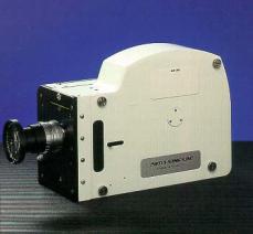
Figure 5. The Photosonics 1PL intermittent, pin registered, high speed motion picture camera capable of 500 full frame 16mm pictures per second. At their top framing rates these cameras that use 16mm motion picture film are able to magnify time by a factor of approximately 20 times. Typical motion picture cameras of this type are the Milliken, the PhotoSonics 1PL (Instrumentation Marketing Corp, San Diego, CA) and the Locam (Visual Instrumentation Corp., San Diego, CA). Larger format cameras can generally not reach these speeds while smaller format ones exceed it at the cost of lower spatial resolution. Rotating prism cameras When the framing rate of the intermittent motion picture camera is not high enough, camera designers compromised somewhat with the sharpness of the records obtained and designed cameras in which the film is in constant motion during the filming process. Since the film never comes to a standstill, the image of the subject must be moved at a rate that matches as well as possible the rate at which the film is moving. Then a simple segmenting device allows the moving film to periodically record the appearance of the subject.
Figure 6.Representation of the method whereby the rotating prism moves the image along with the film in a rotating prism high speed motion picture camera. The device that accomplishes this requirement is a glass block that rotates and is placed between the lens and the moving film. The image forming rays pass through the rotating block and are deflected so that the image formed by the lens moves at the same rate as the film. As the critical angle between the incoming light rays and the glass block is exceeded the illumination at the film plane decreases (essentially "shuttering" the view) until such time as the next facet of the block starts to transmit the next view of the subject onto the film.
With interdependent gearing, the glass block and the film maintain a relatively stable relationship to each other as the film is pulled through the camera from a supply spool onto a take-up spool. Cameras are available that accept film loads from 100 to 2,000 feet of 16mm film (4000 to 80,000 frames) and the framing rate is essentially dependent on the rate at which the film can be moved through the camera. Special circuitry is available in some models to reach and keep the preset framing rate as constant as possible.
Figure 7. Relationship of component parts of the film transport and image motion inducing rotating glass block in a rotating prism high speed motion picture camera. Ultimately, accurate timing can only be accomplished by the fact that timing lights, flashing at known time intervals (generally 100 or 1000 flashes per second) are incorporated into the cameras and these leave a periodic mark on the edge of the film. If the time between marks is known then the number of frames between marks is an indicator of the camera's framing rate at the time the timing marks were impressed on the film.
Framing rates up to about 10,000 full frame 16mm film images per second can be reached for relatively long times. At such framing rates the time magnification ability of these cameras is about 400 times. Some cameras can be equipped with magazines holding up to 2,000 feet of film and while top framing rate may be compromised, recording time can be significantly extended. When even higher framing rates are desired these cameras can be equipped with prisms containing a larger number of facets and this allows doubling or quadrupling the full frame capability of the camera by respectively reducing the height of the individual frames to 1/2 or 1/4 their full frame dimension. Refinements of this basic concept of glass-block motion compensation include cameras where the compensating device is a multifaceted mirror ground onto the same shaft that advances the film through the camera. Cameras of this general type include the Fastax, Hycam, Nova, PhotoSonics 1b (Instrumentation Marketing Corp., Burbank, CA), Photec, etc.
Rotating drum and mirror cameras Again, physical limitations put a ceiling on the rate at which film can be transported through a camera. When still higher framing rates are needed than those reached by the rotating prism cameras, then cameras based on yet a different image motion compensation scheme are available. These can reach higher speeds but usually at an additional compromise on image sharpness due to small amounts of motion between the film and the image during exposure. In these cameras the image forming rays are deflected by a rotating multifaceted mirror driven by a rotating drum that also holds the film during exposure. The mirror turns at a rate set by the camera design parameters so that the image moves at the same rate as the film located along the inside periphery of the rotating drum. The motion-inducing rotating mirror also deflects the image of a "stop", through which the image forming rays pass. As it moves across a physical replica of the stop and because the stop's image is moved more rapidly than the subject's image, the shuttering of such a camera is quite remarkable in terms of duration.
The principle of operation of image motion compensation and shuttering in these cameras is referred to, after its inventor David Miller, as the Miller Principle.
Cameras like this only hold enough film for about 200 separate full-frame 16mm pictures but can achieve recording rates of up to about 35,000 pictures per second at exposure times for each frame of less than a microsecond. Such a relationship obviously means that the camera is out of film in less than 1/100 second when running at full speed but the framing rate is uniform along the film and generally no timing lights are needed. One simply needs to make a record of the framing rate the camera was running at during the recording. This is displayed by a simple tachometer readout.
Figure 8. Diagrammatic layout of the Cordin 350 Dynafax rotating mirror and drum high speed camera. 1 Objective lens, 2 Mask, 3 Field lens, 4 Capping shutter, 5 Entrance stop, 6 Entrance relay mirror, 7 Entrance relay lens, 8 Rotating hexagonal mirror, 9 and 9' Collimating relay lenses, 10 and 10' Exit stops, 11 and 11' Imaging relay lenses,12 and 12' Exit relay mirrors,13 Film
Unlike most other cameras, drum-type cameras generally do not need any sort of synchronization scheme between the camera and the event as long as the event is self-luminous. It is said that they are "always alert". This is a result of the camera running the same film past the image gate over and over at the desired framing rate. The drum is simply brought up to the desired speed and when an event happens it turns on a bright light and the event gets recorded by the film. One only needs to close a shutter (or use a light that lasts less than one revolution of the drum) before the drum has made a complete turn to prevent multiple exposures.
Their framing rate, and thus time magnification capability, is high but the images captured by these cameras can generally not be conveniently viewed with a projector. They are, instead, viewed as a series of still images or are "animated" by duplication onto standard motion picture stock. Cameras of this type include the Dynafax by the Cordin Corporation, (Salt Lake City, UT).
Figure 9.Sequence
of schlieren photos made at 20,000 pictures per second with a Cordin Dynafax
rotating drum and mirror high speed camera.
Rotating mirror framing cameras
When even higher framing rates than 35,000 pictures
per second are desired a compromise is then typically made in terms of
the total number of images acquired. For photography at rates of millions
per second, the film is actually held still and the image of the subject
is moved to successive positions by means of a rotating mirror. The primary
image collected by the camera's objective is brought to a focus and is
then re-imaged on the surface of a rotating mirror. This mirror is surrounded
by an array of lenslets which in turn re-image the subject's image formed
in the mirror onto film which is held in an arc at the appropriate distance
from each lenslet.
Figure 10.Basic layout of rotating mirror ultra high speed framing camera. Since each lens can only "see" the image of the subject reflected by the rotating mirror when the mirror is lined up at a particular angle, as the mirror rotates each lens records the view of the subject at a slightly different time than the other ones. The time between lenslets recording their respective images is a function of how fast the main, rotating, mirror can be made to turn. With rotation rates of thousands of revolutions per second, framing rates of millions of pictures per second are possible, albeit for only a few microseconds duration or only a dozen to a few dozen frames. Again, framing rates with these cameras can be increased by making the frames small when measured in the direction of mirror rotation. To prevent multiple exposures, that would be caused by the main mirror making more than one revolution, a variety of capping shutter schemes are employed both before event initiation (in case of a non-self-luminous event) and post-event. These include mirrors or glass windows that are explosively shattered as well as surfaces explosively coated with various materials. Timing and synchronization are significant problems when using these cameras. Image dissection cameras Framing rates of 100,000 pictures per second and higher can also be achievedby cameras that sacrifice spatial resolution for temporal resolution by using the same piece of film to store information about the appearance of the subject at more than one time. This solution to high speed recording depends on the fact that it is possible to demonstrate that one can often make do with images of low spatial resolution and still have enough information to deduce various subject behavior parameters. By placing a grid consisting of a fine opaque/clear lines in front of a piece of film, and assuming the clear lines to be 1/10 the size of the opaque ones, it can be readily understood that if a picture is made through the grid only 1/10 the film's surface area will be exposed. If the grid lines are small enough a fairly good representation of most subjects can be achieved with only 1/10 the total image content information possible. Then, by moving the grid a distance equal to the width of the opaque grid it is possible to make additional records of a subject. It the subject is in motion during the time that the grid is in motion, the image information will occupy different locations on the surface of the film. Once the film is processed, the real grid is placed on the film and registered with its location when the picture was made. Then, movement of the grid across the grid lines presents the viewer with essentially a brief "motion picture" of the subject's action during the time the grid moved while the "sequence" of pictures was being made. Obviously synchronization is a major problem. Cameras of this type are quite rare but are able to achieve very high framing rates at relatively low cost. Electrostatic image tube cameras An alternative to high speed rotating mirror framing cameras and image dissection cameras is the high speed framing electrostatic camera based on the use of an image tube, sometimes equipped with an auxiliary micro-channel plate image intensifier. A camera of this kind is the DRS-Hadland Imacon. In these cameras, capable of making images with a time separation of the order of a few nanoseconds, images are electrostatically shuttered and moved to various locations. These are eventually recorded on a sheet of film (often Polaroid sheet film or, in newer versions, on CCD arrays) such that eight to ten images appear on a single sheet. This means that while the framing rate of these cameras is the fastest among all high speed cameras, the number of records is among the fewest. High speed video and CCD systems The high speed industry was to a large extent stagnant in terms of new developments in instrumentation until recent developments in electronic imaging detectors and integrated systems made significant inroads into a field long dominated by film-based cameras. Early high speed video cameras were no match for the workhorse of the high speed industry: the rotating prism high speed camera. This situation changed dramatically with the introduction of the Eastman Kodak (Rochester, NY) Ektapro system which, when introduced, was capable of capturing and storing 1,000 full frame video images per second with a sensor made up of 192x240 pixels. At first novel tape transport methods allowed the system to store images on videotape. While the system captured black and white images at a significantly lower resolution than film the immediate availability of the data and the fact that the equipment did not require a skilled operator made it a highly desirable imaging tool in the manufacturing industry.
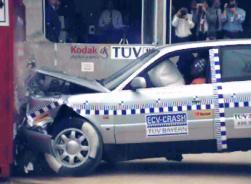
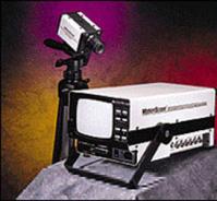
Figure 11a.One frame taken out of a motion record captured by a high speed digital camera at 1000 frames per second of a car crash test. Made with a RedLake motion scope camera. Figure 11b.The Redlake MotionScope digital high speed camera. A newer version of the system, the EM, as well as several "close-cousins" of the fundamental design, store several thousand full frame images in RAM digital memory. This enables the camera to achieve something that the high speed industry has sought to accomplish since the advent of photography. This is the recording of random events at a high recording rate and the visualization of a subject's state just prior to, as well as during and after, catastrophic failure.
This is accomplished by erasing the oldest images recorded into RAM memory while continually adding new images to the "image stack" loaded into the camera. By monitoring the event the camera is made to stop recording at some suitable time after a random event happens and the stored images are then played back from a time prior to the initiation of the event or failure.
Advances continue to be made in the area of solid-state imaging and high recording rates at brief exposure times are currently achieved in a similar fashion. Often microchannel image intensifiers are used to boost the light sensitivity of these high speed imaging systems.
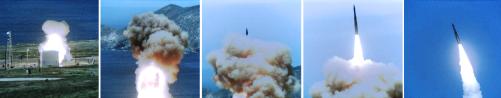
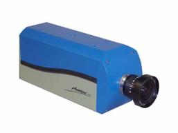
Figure 12a. Minuteman missile launch recorded at500pps by a Photosonics Phantom digital high speed camera.
Figure 12b.Phantom high speed digital camera
Streak and Strip cameras The imaging scheme used in cameras of standard design is that the film remains stationary with respect to the film gate at the time of exposure. A significant number of specialized applications employ cameras in which the film is in motion at the time of exposure. In their simplest manifestation film is simply moved past a stationary slit and the exposure itself takes place during the transit of the film across this opening. Unlike normal cameras that make photographs that have two spatial dimensions, these "strip or streak" cameras always display time as one of their dimensions and one subject spatial dimension as their other dimension. When cameras of this type are used to make records of subjects whose images don't move across the shutter-slit they are basically simple time-recording instruments. When images move along the slit then the photographic record can be reduced to image velocity or acceleration. Cameras that employ this scheme for making photographs but whose output resembles the subjects they are photographing depend on moving the image of the subject at the same rate as the film moves past the stationary, slit, shutter Streak Cameras In its simplest form, the camera system described above basically behaves as a light-based strip chart recorder where a physical pen is substituted by many light "pens" operating along the open slit-shutter of the camera while the moving film is the recording medium. As such, the instrument is capable of making precise measurements of event duration, simultaneity, velocity, acceleration, frequency, etc.
Figure 13. Diagrammatic layout of a high speed rotating mirror streak camera. The time resolution of the camera is first a function of the rate at which the film can be moved past the slit and second on the width of the shutter-slit itself. When the upper limits to film transport methods are reached, the image of the slit can be quickly wiped across stationary film. Rotating mirror streak (or velocity recording) cameras have been made with time resolutions of better than 1 cm per microsecond and slit sizes as small as 1/10 of a millimeter and less.
Electrostatic streak cameras are designed so an image line is deflected electrostatically across the face of an image tube for time resolutions that enable researchers to determine the duration of events in the picosecond time realm. Hamamatsu, (now DRS-Hadland) and EG&G are two companies that produce such streak cameras.
Strip Cameras
When it is desired to make a record of a scene so it resembles its appearance to the eye, the image of a subject can be made to move across the slit-shutter of the streak camera, instantly converting it into a "strip" camera. Images can be made to move across the slit of the camera by several methods. The easiest by far is to simply have the subject move in linear fashion across the field of view of the lens. There are two major applications for this imaging method in high speed photography.
Figure 14. Diagram of a moving film strip (or streak) camera. In the strip or synschroballistic and photofinish mode the images move in the same direction as the film. In the streak mode images move perpendicular to film motion direction.
Synchroballistic and photofinish photography Synchroballistic photography is a high speed photographic technique used to photograph fast moving objects such as rockets in flight. It is also the same process that is used to determine accurately the order of finish of horses at racetracks. There are several problem associated with the making of high speed pictures of high speed missiles in flight. The major one is that until lately it was impossible to make shutters that had good light transmission characteristics and gave a short exposure time to make sharp pictures of these objects. Missile photography using a high speed motion picture camera could be used but there is a problem with tracking the missile as well as with using large amounts of film and finally the pictures are generally small. If such photographs are magnified to any extent the results are not of very high quality. The solution is the "synchroballistic photography" system. In this approach the problem of high subject speeds, and consequently image speeds, is solved by putting the film in motion. The film is moved in the camera at the expected speed of the image of the missile. Since the image and the film are moving a the same rate, the film sees an essentially stationary image of the missile recording each part of the missile at a different time. In a synchroballistic camera (as well as in a horserace photofinish camera) there is generally incorporated a narrow slit shutter just in front of the film plane. The film is transported past this open slit while the image of the object being photographed also moves past this slit at the same speed as the film moves. Thus the film records, sequentially, the image of the object as it moves past the slit. The final record, then, is a view of one line in space spread out over time. The cameras depend on good a priori knowledge of the speed that a missile will be traveling at in order to end up with sharp pictures but this is often a solvable problem. Ultimately the photographs these cameras deliver are sharp, they are full of detail, they provide quantitative information and they are relatively inexpensive. A "drawback" is that sometimes the images look distorted from their real appearance but information content is still very high. A variation on the theme is the application of these cameras at racetracks. In this case, horses are substituted for a missile and as the image of each horse passes over the slit the horses are recorded sequentially onto the film. The film speed is adjusted to match that of the image of the average racehorse. As each individual "nose" gets to the slit of the camera it is recorded sequentially. Of course, the noses are followed by therest of the body of the horses and they too get recorded eventually as they move forward. But the important part is that the sequential arrival of each nose to the slit on the "strip" camera is then displayed in offset and on different positions on the film or final print. The distance between noses can be directly translated to difference in the time of arrival of each nose at the slit of the camera which is lined up so that it matches the finish line on the real track. This system is much better than trying to determine the order of finish of racers based on human judgment, or on a single photograph or on a motion picture sequence. The picture presents, on a single flat sheet of paper, the order of arrival of the horses, accurately, with a high degree of reliability and without a doubt caused by loss of time information. Electronic or "digital" strip cameras are currently being installed at many racetracks. They are "linear" array cameras where a single row of CCD sensors doubles for the slit of the film-type strip camera. The results are similar to what was traditionally achieved but the darkroom is no longer needed. Several linear array cameras can be installed along the track for basically instantaneous readings on the elapsed time for any given racer between the start and the arrival at a given location as well as obtaining accurate, almost real time, time-between-racers information even as the race is developing. At the high end of high speed photography or time-resolution instrumentation cameras like this, or variations on the theme, are used to detect whether lasers hit targets simultaneously in nuclear fusion research.
Photographic Techniques often associated with High Speed Photography.
Basic Flow Visualization Techniques
Photography is widely used to visualize phenomena that are invisible to the eye by virtue of the fact that they hardly alter the environment from a visual point of view. Such events are associated with density gradients formed in liquids or gases as a result of non-homogeneous mixing or the by-product of local heating, cooling or compression of gases. To visualize these gradients several basic techniques are used.
Shadowgraph method
The shadowgraph is the result of interposing a subject containing density gradients between a small (sometimes referred to as a "point") light source and a screen (often plain photographic film or paper). The gradients present in the subject cause light rays to fall in different locations than they would if the disturbing medium were not present and therefore the effect of the gradients on the light distribution on the screen can be then associated with the gradients themselves.
Figure 15. Diagram of layout of a direct shadow (shadow cast onto film) and reflected (imaged by a camera) shadowgraph systems.
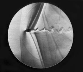
Figure 16. Mircosecond illumination direct shadow shadowgraph of bullet in supersonic flight.
If a plain screen is used a standard camera can be aimed at the screen from the front or, if the screen is translucent, from the rear. High reflectivity (3M's Scotchlite (R)) materials allow the visualization of shadowgraphs in daylight conditions.
When photographic materials are used as the screen, the system is set up under laboratory conditions in a darkened room and the lamp is placed in a shuttered enclosure or a flash is used as the source. Advantages of this simple system are its ability to deal with large subjects and low cost. A disadvantage is its relatively low sensitivity.
Schlieren methods
When a higher level of sensitivity is desired optical elements are incorporated into the shadowgraph system (thus practically limiting the size of the subjects that can be photographed) and deviations in the path of light rays caused by density gradients (or departures from surface flatness in reflective systems) cause these deviated rays to interact with various physical obstacles (knife edges) emphasizing the appearance of these gradients compared to their appearance in a shadowgraph system.
Single pass Schlieren systems
In a popular layout, a small light source is placed at the focal point of an astronomical-quality spherical or parabolic mirror (lenses can also be used but the system costs go up dramatically). The light emerges from the mirror in a parallel beam intercepted some distance away by another similar mirror. It collects the light rays from the first one and brings them to a focus at the focal point where a real image of the light source is formed.
Figure 19. Layout of a conventional double-mirror, or "Z" configuration, schlieren system.
Figure 18. Bullet in flight by schlieren technique< The light continues into a camera where the image of the second mirror's surface appears to be filled with light. Introducing a "knife edge" into the image of the source causes an overall drop in the light level of the mirror's surface. When the image of the source is moved by refractive index gradients in the space between the source and its image, local variations in light level appear in the image of the second mirror's surface. Photography is almost secondary to the process although just about every industrial Schlieren system is designed with a camera of some sort incorporated in the system. Double pass Schlieren systems. When the sensitivity of the above design is not sufficient, light can be made to pass through the density gradients twice and thus the sensitivity is increased. This is commonly accomplished by using a single mirror and placing the camera and the source close to each other and both located approximately two focal lengths from the mirror's surface. In this fashion a life-sized image of the source is formed just in front of the camera lens.
Figure 17.< Diagrammatic layout of a single mirror, double pass or sensitivity, schlieren system.
The light from the source again proceeds into the camera lens where it contributes to making the mirror's surface appear to be fully luminous. Intercepting some of the light rays at the image of the source leads to an overall, uniform, darkening of the image of the mirror's surface (as if the source itself had been reduced in size or its luminance decreased).
If the knife-edge remains fixed in position and the image of the light source is moved (by density gradients) then those areas in the image of the mirror's surface made up of light rays that moved away from the knife edge will appear brighter. Those made up of rays that moved towards the edge will appear darker than the brightness level associated with a steady-state condition.
Replacing the opaque, solid, knife edge with transparent, colored, filters opens up the possibility of introducing color into the images although color systems, while visually more appealing, are often of lower sensitivity than black-and-white systems and do not generally yield additional data.
Focusing Schlieren systems.
An interesting schlieren scheme that overcomes the relatively high cost and complexity of mirror systems, while not loosing much in terms of sensitivity to them is the focusing schlieren system. This system is particularly well suited for dealing with windows (in wind tunnels for example) of relatively low quality and has the advantage of being highly sensitive to the location of the gradients in the scene, unlike mirror systems which are influenced by the effect on light rays over the entire distance from source to knife edge.
A basic focusing schlieren system consists of a grid of opaque and transparent lines placed in front of a broad light source. A camera lens, although focused at some distance between it and the grid (where the subject will be located) forms an image of the grid located some distance on the opposite side of the lens but closer to the lens than the subject plane it is focused on. The image of this grid will be distorted to some extent and may be rather badly distorted if low quality windows are placed between the grid and the lens. Whatever the quality of the image is, a reproduction (negative) of it is made onto high contrast film.
Figure 20. Essential components and layout of a focusing schlieren system.
After processing, the photographic negative is then replaced in the same exact position that it had when the image of the (distorted) grid was made. The consequence is that the negative image of the grid prevents any light rays from proceeding onto the camera's ground-glass and the field is completely (or mostly) dark. The subject giving rise to, or containing, the refractive index gradients is now placed in the location that the lens is focused on, between the light source and grid combination and the camera lens. Since it is closer to the lens than the grid an image of it is formed beyond the distance at which the image of the grid was brought to a focus and where the negative of the grid is placed. Disturbances in the path of light rays are now induced at the subject location will cause some of the light rays making up the image of the grid to move relative to the obstructing negative and those areas on the ground-glass will gain brightness identifying a subject with non-homogeneous refractive index distribution. If direction changes are caused in locations outside the plane of sharp focus of the lens they tend to move the image of the grid over a much larger area and simply slightly degrade the overall contrast of the image but can not be identified with a particular location. Reflection Schlieren systems Generally only transmission schlieren systems are used but a significant tool for determining surface flatness of reflecting or semi-reflecting surfaces can also be investigated with a reflection schlieren system. In this scheme the light source and camera lens are again next to each other but located one focal length from a "field" lens. Since the source is at the focal point of the lens a parallel beam of light emerges from it. If this falls on a flat surface and is reflected directly back to the lens, then an image of the source is formed again at the focal point of the lens. Since the lens and source can't generally made to occupy the same location they are each slightly off-axis. If the surface is not flat then it changes the direction that the light rays are reflected from the surface. When these changes are at right angles to the orientation of the knife-edge this causes variations in light intensity at the image of the lens' surface. The change in direction can be caused by either the surface not being flat or by refractive index gradients being present in the space between source and image. One attempts to isolate the changes to a known location, generally as close to the flat mirror as possible. Surface qualities of multiple surfaces can be visualized by offsetting slightly the angle of tilt of each individual surface. Each will produce an image of the source and thus multiple knife edges are used.
Bibliography/references: 1. Arnold, C.R, Rolls, P.J., Stewart, J.C.J, Applied Photography, edited by D.A. Spencer, Focal Press, London, UK 1971 2. Sidney Ray, Editor, High Speed Photography and Photonics, Focal Press, Butterworth-Heinemann Oxford, UK 1997 3. R.F.Saxe, High Speed Photography, Focal Press, London, UK 1966 4. Harold Edgerton, Electronic Flash, Strobe, the MIT Press, Cambridge, MA 1987 5. E. Hecht, Optics, Adison Wesley, Reading, MA 1987 6. Proceedings of the International Congresses on High Speed Photography and Photonics starting from the first meeting in 1952. Recent issues published by the SPIE, the International Society for Optical Engineering, Bellingham, WA.
High Speed and Photoinstrumentation Companies:
EG&G |