|
Digital strip (slit scan) camera based on a standard digital SLR camera Andrew Davidhazy School of Photo Arts and Sciences Rochester Institute of Technology Link to main ARTICLES page Strip cameras (sometimes referred to as "slit-scan" cameras) are used for a variety of applications. One of the most popular ones is their use at racetracks to determine the order of finish of race participants. These cameras are available as film based systems but recently they have also become available as their digital equivalent and are sometimes characterized as "linear array" digital cameras. The "claim to fame" (and usefulness) of linear array cameras is that they incorporate TIME as one of the dimensions of the record they make. This capability lends them to become useful photographic tools for a wide variety of applications. Besides serving a photofinish cameras they can be used to make peripheral records that show all sides of a subject on one flat reproduction. They can also be used to make 360 degree panoramic records by the simple expedient of rotating the camera while the array gathers subject information, etc. The major problem with these cameras from an average user's perspective is that they are specialized and thus tend to be expensive. I thought there might be an alternative. An improvisation if you will. One that would compromise on a number of high end capabilities of commercial systems but one which would allow experimenters and students to explore certain applications of linear arrays without the expense of having to purchase such a camera. At the heart of the improvisation is the realization that in a real linear strip camera the array records what is happening on the line of pixels over time and then this is displayed on a display or computer screen. The clocking rate of the array, or the number of times per second that the array is sampled, is controlled by the photographer. This allows for adjustments to be made so that the aspect ratio of the reproduction of any given subject closely matches that of the original subject. But this article is not so much about how real strip cameras work but about how to improvise one! 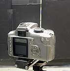 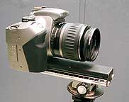 With this
in mind, since the sensor in a digital camera is a 2
dimensional one the first step is to make it appear to be a 1
dimensional one (which is what a linear array is). Since this can not
be done within a camera the option is to do it outside the camera. This
can be done by making the camera look at the subject through a narrow
slit as shown in Figure 1. With this
in mind, since the sensor in a digital camera is a 2
dimensional one the first step is to make it appear to be a 1
dimensional one (which is what a linear array is). Since this can not
be done within a camera the option is to do it outside the camera. This
can be done by making the camera look at the subject through a narrow
slit as shown in Figure 1. Figure 1. Figure 2. Figure 3. (below) 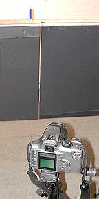 When the camera is
first set-up this way it is useful to place a thin,
vertical subject on the other side of the slit "assembly" made up of
two black panels with a space of a few millimeters between them. In
this case a blue felt tip marker was used as the "target". The
camera is then aimed so that the object appears centered in its
viewfinder and the subject is seem in the center of the slit. The
curtain bearing the slit should not be too close to the camera nor too
close to the subject or area you will be photographing. Experiment with
finding an appropriate location. When the camera is
first set-up this way it is useful to place a thin,
vertical subject on the other side of the slit "assembly" made up of
two black panels with a space of a few millimeters between them. In
this case a blue felt tip marker was used as the "target". The
camera is then aimed so that the object appears centered in its
viewfinder and the subject is seem in the center of the slit. The
curtain bearing the slit should not be too close to the camera nor too
close to the subject or area you will be photographing. Experiment with
finding an appropriate location. The camera needs to be mounted on an adjustable holder that allows the camera to be rotated about an axis other than that defined by the tripod socket built into the camera. A rack and pinion device as shown in Figure 2 is useful. Such a camera holder can be improvised I am sure. Once the camera is aligned as discussed earlier it is rotated left and right while watching the object in the background as seen within the slit. If the object seems to move as the camera is rotated and the image of the slit moves from one edge of the viewfinder to the other then the position of the camera is adjusted and the process tried again. One does this until such time as the object remains stationary an d within the slit while the camera sweeps the image of the slit from one side of the viewfinder to the other. This is the same type of adjustment applied in panoramic photography to make sure that the camera rotates about a point that keeps foreground and background subjects fixed. With the camera rotating about this point the spatial relationship between foreground and background object remains unchanged as the camera scans a scene. In this case the object beyond the slit remains visible within the slit even though the slit may be located at the left or right edge of the camera's viewfinder. Review Figure 3. Once this is accomplished the camera is aimed to one side of the slit and with the camera set to a relatively long exposure time, maybe a second or two, and at the time the shutter opens the camera is rotated so the camera is now pointed to the other side of the slit bearing "curtain". Keeping the light aimed at the subject and preventing it from falling on the black panels defining the slot is advisable since they will be exposed for the full duration of the sweep of the camera. While the shutter is open the image of the slit, and whatever is beyond the slit, are swept across the camera's sensor. If the object was stationary then the sensor will display a continuous "streak" or streaks extending from one side of the frame to the other. This is shown in Figure 4 at the left below. This and the next two figures are the very first three exposures made to test the feasibility of the idea. They have only been adjusted for tonal value but nothing else. 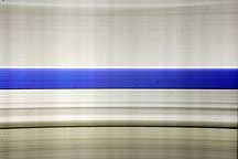
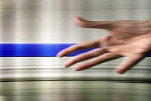

Figure 4.
(streak mode) Figure 5. (steak and
strip mode) Figure 6.
(strip mode)
If while the camera pans from one side to the other an object "travels" behind the slit in front of the camera its passage will be recorded by the camera exactly the same way as it would have been recorded by a camera equipped with a linear array. This is shown in Figure 5 above. The system made a streak record of the blue, stationary, object and a "strip" record of the moving hand. In the next figure a spray can was placed on a turntable and rotated while the camera was panned from side to side. This yielded the encouraging promise that the system would be capable of making what is called a peripheral or rollout photograph of the can. The result s seen in Figure 6. These photographs are obviously not "finished" pieces but they are a "proof of concept" and that is of great value as it opens the door for more controlled experimentation. The next two figures, both rollout records, are images that were made with the objects placed on a regular phonograph turntable rotating at 72 rpm and while the camera was panned from left to right across the slit over a time of about 4 seconds. In the first instance it is obvious that the recording or panning rate of the camera yielded a more "normal" looking reproduction of the label on the can. The fact that the labels are not all the same width indicates that the camera panning rate slowed down a bit where the label seem to be compressed (on the left). This is also indicated by the fact that the left side of the image is slightly lighter in tone indicating more exposure caused by the image of the slot moving more slowly across the sensor. 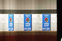
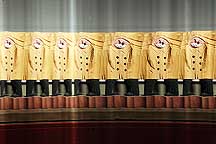
Figure 7.
Figure 8.
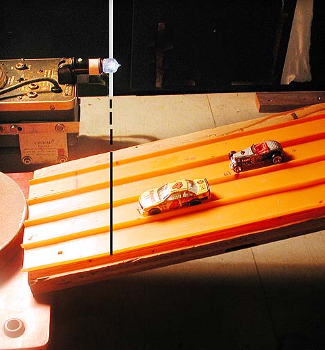
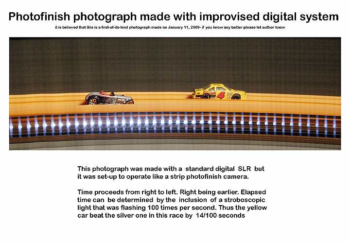
This improvised system obviously can't compete with real linear array cameras but it opens up possibilities for creative experimentation. The system can also be used for several quantitative analysis applications for which one would normally use an expensive commercial linear array camera. Subjects that come to mind in this area are the determination of duration and simultaneity of events. It could certainly be used as an improvised photofinish camera although the total recording time may be somewhat short. Inclusion of a flashing light from a calibrated stroboscope would provide a known time-base along the length of the images. If objects moved up-down along the slot then velocity and acceleration could be measured by adding a vertical scale along the slot. The applications are endless! Here is an example of a table-top demonstration of how this improvised arrangement was used as a "demonstration quality" photofinish camera. Click on the picture at right to see this described in another way. Finally it is worth remembering the point here is not so much to dwell on limitations but to explore and exploit new possibilities opened up by this novel approach to imaging. If you have any questions about this
project or questions related to
strip or streak or slit-scan cameras specifically feel free to contact
me by email
at:
Andrew Davidhazy, andpph@rit.edu |