|
Projection Crystallography and Micrography with Digital Cameras
Andrew Davidhazy During a lunchroom conversation many years ago a good friend of mine, by the name of Nile Root, and I observed that a microscope is very similar to a photographic enlarger and we proceeded to introduce this concept to our classes. Eventually a student of mine by the name of Alan Pomplun wrote and article about the technique of using an enlarger as the basis for photographing crystals that exhibited birefringence. The reasoning was that in some applications a low magnification of crystalline subjects typically examined in crystallograohy was acceptable and that the light beam in an enlarger could be easily polarized above a sample placed in the negative stage. A second polarizer placed below the lens would allow the colorful patterns that some crystalline structures achieve to be come visible. His article, that was published in Industrial Photography magazine in 1988, can be retrieved here. With the advent of digital cameras the process of using an enlarger as an improvised low-power transmission microscope merits to be revisited as there are many benefits to be derived from using the digital process for the capture of images under such a "microscope" but there are also potential pitfalls to be aware of.
To accomplish such magnifications all one needs to do is to capture the image formed by the enlarger onto the electronic sensor of a digital camera (such as a Canon Rebel Digital or similar) and then examine a small fraction (possibly a 1/10th) of the total frame to experience truly amazing magnification results.
You will also need to make a second block whose thickness is just equal to the thickness of the camera's cradle plus the distance from its back to its image or sensor plane. The camera's image plane location is typically indicated by a circle with a line through it. The line is the location of the image plane.
The focusing/composing block's image location vs. sensor location in the camera itself should match when the camera cradle and focusing block are each slid up against a given corner on the easel or some other locating guide on the easel or enlarger baseboard. I prefer to use a Saunders metal easel due to its weight and rubberized pads which prevent the easel from easily sliding away from a desired position. This assures that when the focusing block is taken away and replaced by the camera cradle the camera's sensor will line up quite accurately with the area on the focusing block that indicates the location covered by the sensor in the camera. For photography, the subject (possibly some simple large celled membrane such as an onion skin) is placed on a glass carrier, such as a microscope slide or a photographic slide cover glass, in the enlarger where the negative would normally be placed. The translucent cells are enlarged by the enlarger to a convenient size and framed as desired using the focusing/composing block as the guide. The enlarger lens' aperture should be set to some value below maximum aperture but not the minimum one. It is best to choose a mid-range aperture such as f/8 or f/11. Anything lesss than that will typically cause diffraction effects that lower sharpness.
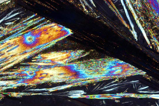
The following steps are performed in a dark environment very much like the darkroom that a photographic enlarger was originally designed to work in. With ambient lights out and the enlarger on, a section of the image of the subject that is projected by the enlarger's lens is selected using the focusing block as a guide and ultimately it is replaced by the camera cradle carrying the camera on its back facing the enlarger's lens. With the enlarger throwing an image towards the camera's sensor the camera is tripped and an exposure is made. It the manual shutter speed was selected one looks at the resulting image in the monitor and/or checks the histogram of the image (if available) to check for proper exposure and makes another exposure at an adjusted exposure time if the first one yielded inadequate overall results. If the programmed or aperture priority mode were chosen then the camera probably arrived at an exposure that was approximately the correct one without much "operator adjustment' required. Interesting results can be achieved by magnifying many small "critters" such as simple organisms collected from stagnant pond water although these tend to move about and make photography a challenge. Items that produce visually striking images are crystals that exhibit birefringence. Placement of such crystals between polarizers causes color to appear in a subject as if by magic. If plane polarized light is allowed to impinge on a sample (by passing light through a polarizer) and the plane of polarization of the incident beam is turned by a particular sample enough so that it is crossed with that of a second, analyzer, polarizer then the color perceived in that region of the sample will be that of white light minus the wavelengths that were eliminated by the second polarizer. This technique is sometimes called projection crystallography. The samples or subject that are suitable for initial experimentation are prepapred by simply allowing solutions containing various crystals to evaporate thus causing the crystals to crystallize out of solution onto a transparent substrate. Once the crystalline form of the materials is visible these are placed in the enlarger's stage and a polarizer is placed above them. Samples can also be prepared by melting various crystals using a heating element or a bunsen burner to warm up the glass slide carrying the dry crystals. If crystals with a low meting point are chosen then these will recrystallyze upon removal of heat and possibly forma interesting visual patterns. Note that during the process of melting some crystals emit nixious fumes and safe handling precautions should be followed. Melting such materials outdoors or under a fume hood is advisable. A second polarizer is placed either directly below the enlarger's lens or it could even be placed on the body flange of the camera. Placement of the filter here precludes easy inspection of the colors that the camera will record but it prevents dust from falling onto the camera's imaging sensor. Dust should not be a problem if you are careful. While the polarizer used above the subejct can be an inexpensive "linear" type it is best if the second polarizer is a "circular" polarizer. These are polarizers that essentialy depolarize polarized light that is incident on one of their surfaces so that the exiting light is no longer polarized. These filters are required for proper exposure determination by cameras equipped with metering systems that operate through semi-transparent mirrors, etc. Most digital SLR cameras have such metering built in and benefit from the use of circular polarizers. The placement of such a polarizer should be anywhere below the enlarger lens and its orientation should be the same as it would be when placed on a camera lens with respect to the direction that light is incident on the filter. Namely the font of the filter should be aimed at the enlarger's lens. Note that if you inadvertently install a "circular" polarizer in place incorrectly (upside down vis-a-vis its correct orientation), the birefringent effect will be very small or possibly completely nonexistent. The reason for this is that the "1/4 wave plate" bonded to the linear polarizer portion of a circular polarizer will depolarize the polarized light coming down to it from the sample and so it will not have a chance to subtract out any light preferentially by color as a plain linear polarizer would. Or as a circular polarizer with its linear polarizer component facing the enlarger's lens will also.
Onion skin cells Photographic fixer
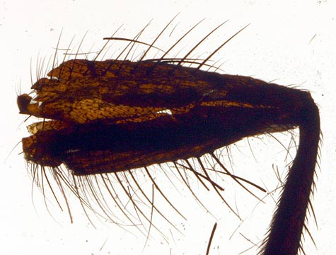
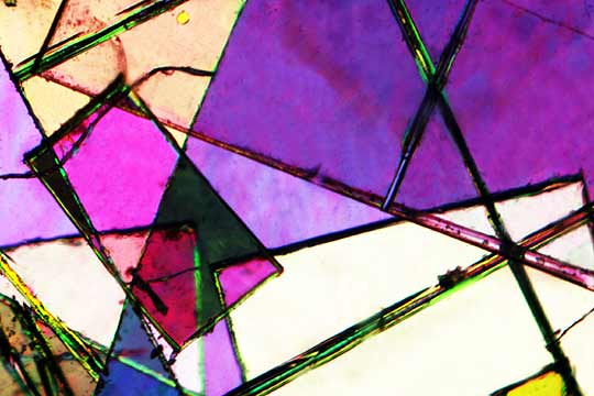
Leg segment of a fly Cellophane pieces These photographs were made as described in the above article. They were originally magnified by the enlarger lens directly onto the camera's sensor at a magnification of about 8x. The Canon Digital Rebel recorded these images onto its 15.1 tall by 22.7 mm wide sensor and this image information when displayed at 72 ppi (as on most CRTs) would measure over 42 inches (or 1066 cm) in width and thus we might say that on a CRT the camera image is magnified a further 46 times or so. So the total magnification of the system might be about 360x although realistically some of this is what is called "empty" magnification as fine detail is not uncovered or discerned beyond a limited value that depends on various factors beyond the scope of this article. In any case, projection crystallography and low-magnification transmission microscopy hold much promise for hours of fun and instructional experiences and might result in some visually stunning photographs to boot!.
If you would like to discuss this project with me I would be happy to provide whatever assistance is needed. Contact me at RIT, 70 Lomb Memorial Dr., Rochester, NY 14623. Phone 585-475-2592, fax 585-475-5804 ... but the fastest way is to just send me e-mail at andpph@rit.edu
|
![[camera carrying cradle]](text-figures/proj-micro-camera+jig-1a.jpg)

![[focusing fixture and camera position under enlarger]](text-figures/proj-micro-camera+jig-2a.jpg)