How instantaneous is a slaved flash?by Andrew Davidhazy
Photographers use slaved electronic flashes as a matter of course but seldom question the delay that must inevitably be present between the firing of a main flash and that of the second, slaved, flash. This delay is generally insignificant in the context of most applications but in this project my students and I set out to find out just exactly what this delay was in relation to a light activated synchronizer and at the same time also decided to find out what the duration and performance of an electronic flash operated at low power (and thus short duration) was.
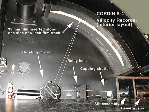
The operating principle associated with a streak camera is that it records a
single line in space displacing it over time on a length of film. The line in
space is obtained by reducing the subject to a single line, e.g. limiting the
height or width of the subject either inside the camera with a slit or at the
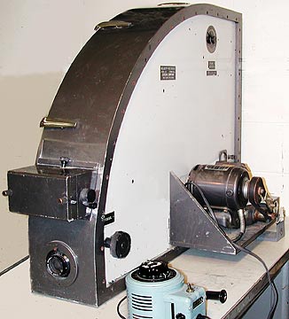
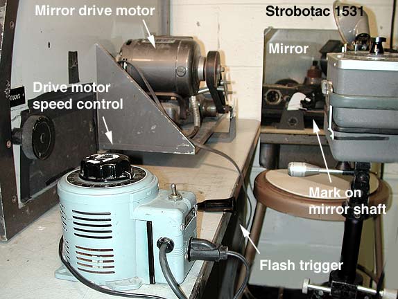
The Cordin S-4 camera was complete except for electronic control devices. However, by driving the motor with a variable transformer we could vary the writing rate of the camera to any desired speed almost up to 10mm per microsecond. Since the camera only records for about a 90 degree arc around the rotating mirror it is necessary to make sure the event of interest occurs while the mirror is in a particular position otherwise the image gets reflected to non-useful areas inside the camera. This is a capability is relatively easily achieved if one had access to the electronic controls normally attached to the camera. Since we did not have such synchronization equipment we solved this positioning problem in a somewhat unorthodox way.
The flash heads were masked down with black photo tape to leave only a 1/8-inch or so wide slot-like opening across each head. We covered one half of each of the two flash-heads with .6 ND filter material. We did this so that we could compare the density produced by the flash both without a filter and with a filter. The density difference would be attributable to a known exposure difference of two stops, or 25% exposure, compared to the unfiltered section. This would allow us to compute the duration of the flash at a predetermined exposure level. The S-4 camera is actually designed for 5" wide film but lacking that we loaded 35mm film slipping it into the edge channel on the inside wall of the camera that normally would have carried the 5" film. We secured the other edge of the film to the curved channel with double-sided sticky tape. This loading process was obviously carried out in the dark. Prior to final loading, the camera, loaded with dummy 35mm film, was aimed at the two flash-heads and the distance adjusted so that they would fall across the 24mm dimension of the film. The camera is equipped with a capping shutter to prevent pre-exposure or post-exposure of the film segment but we did not need to use such a shutter, as the electronic flash discharges were not expected to last a full revolution of the rotating mirror. Thus we disabled this capping shutter.
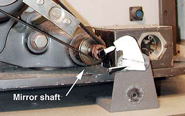
This "writing rate" was determined from a knowledge of the radius the circle that surrounded the rotating mirror. It was 52 cm and so the film track was part of a circle of 326.5 cm or 3265 mm. With the mirror rotating at 10,000 rpm it was doing 166.6 rps or 1 revolution in 1/166.6 seconds. Since the image reflected by the mirror rotates at twice the angular rate ofthe mirror the image was essentially covering 360 degrees or 3265 mm in 1/333.3 seconds. The rate of image motion on the film is, therefore, 3265 mm / 1/333.3 sec. which is 1,088,224 mm/sec or, to simplify matters, 1 mm in 1/1,000,000 second. When the mirror achieved the desired rotational rate of 10,000 rpm the flashes were fired. The light from the flashes was directed by a mirror onto a pointer arrow that was attached to the mirror shaft. If at the time the flashes fired this arrow pointed between a set of predetermined limits on an external marker the experiment was called a success and the film processed. If the arrow did not point within the preset limits the flashes were fired again, and again until it did. Repeated firing of the flashes, even though directly towards the camera lens did not cause any undue overall fogging exposure as the amount of light reaching the film was very small compared to the amount that would reach it when proper placement of the flash discharge was accomplished.
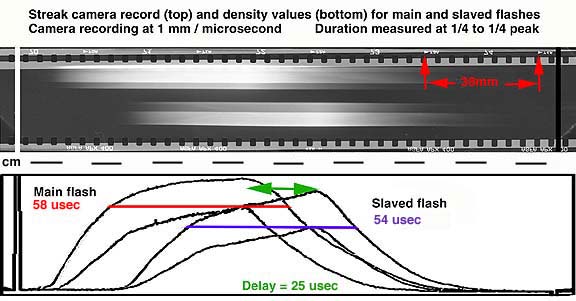
The induction time, or rise time of the flashes to peak intensity is more gradual than the decay time as shown by a visual examination of the density rise and fall on either side of the peak and this is also shown graphically by the density trace along the exposure "bands" caused by the discharge of the flash units. Conclusion: Under most pictorial applications the small time delay associated with the slaving of one flash to another using a light synchronizer is insignificant in consequence. However, there is a small delay present. This delay, in the context of the useful duration of each flash is, in fact, significant as it accounts for nearly half of the exposure time associated with each flash. If rapidly moving objects were photographed with this set-up one could expect a double image to be visible due to the slight delay in the discharge of one flash with respect to the other. Further, the action-stopping ability of these flashes operated at low power levels is rather poor since the output is essentially continuously varying in intensity. In general, however, the performance is quite good as the 1/4 peak to 1/4 peak duration is about 1/20,000 second. If you have questions or would like to discuss any aspect of this test send me email at: andpph@rit.edu This article was placed online on October 12, 2003. The project is one that is a part of the Photoinstrumentation course taught in the Imaging and Photographic Technology department of the School of Photographic Arts and Sciences at RIT. It has been a part of the course since the late 1980s. |