Camera for Conical Peripheral and Panoramic Photography
Andrew Davidhazy
Imaging and
Photographic Technology Department
School of Photographic Arts and Sciences
Rochester Institute of Technology
One Lomb Memorial Drive, Rochester, New York 14623
ABSTRACT
This paper is a report on the development, operating principles and applications
of a camera capable of making distortion free peripheral reproductions of
conical objects. In addition, the parameters governing its use for the
generation of conical panoramic photographs are also described. Examples of
both types of applications are included. Suggestions for other applications are
given. A brief review of the operating principles of standard peripheral,
panoramic and linear type strip cameras is included in the introduction to the
paper.
1. INTRODUCTION
The principles governing the operation of panoramic cameras which are capable
of making extremely wide angle photographs by rotating roughly about the rear
nodal point of their lenses while moving film behind an open slit located just
in front of the film surface are well known. Basic relationships are presented
below in general terms to establish a common level of understanding so that the
rest of the material can be presented in the context of where it fits in with
established camera systems.
Among the earliest panoramic cameras of the type described above is the Cirkut
camera, introduced by Eastman Kodak in the late 1800's and which was available
in a wide variety of film sizes. Modern cameras of similar design include the
Hulcherama, the Alpa Rotocamera, the Panalux or Roundshot and the Globuscope.
It is fundamental to fully understand the method by which these cameras operate
to realize that they record subject DISTANCE, or image position, along the slit
and TIME at right angles to the slit. Since in all of the above applications the
velocity at which the film moves is the same at the top and bottom of the slit,
the elapsed time for any given length of film which passes though the camera is
the same at the top and bottom margins of the film.
Panoramic records made with "cirkut" type cameras are made by rotating the
camera about a vertical axis thus scanning the scene in front of the camera in
sequential fashion. The film accumulates the changing image information
presented to it by the scanning camera and eventually builds up a record on a
length of film containing a view of any desired angle even up to (or beyond) 360
degrees. For the record to look sharp the film must move at the same velocity as
the image. This is accomplished by moving a length of film equal to 2pi times
the lens focal length past the open slit during the time for one revolution of
the camera. In actuality it is the rear nodal point to film distance that
matters but since in most applications the object distance is large, the lens
focal length is usually a close enough approximation to this measure.
Related to the panoramic camera, the peripheral camera is not as well recognized
in either the literature or in terms of working models. The cause for this lack
of recognition for peripheral photography is probably due to the fact that this
application is somewhat more specialized. It is interesting to note, however,
that the making of peripheral photographs, sometimes called cyclographs, of
Greek and Mayan pottery, has been practiced since the late 1800's in a number of
major museums and also in industrial situations.
Peripheral records of the surface of cylindrical subjects can be easily made by
rotating the subject in front of the camera. The film in the camera is made to
move at right angles to the axis of rotation of the subject and in the same
direction as it's image. The slit restricts the angle of view along the axis
paralell to film motion to a very narrow angle, thus it encompasses only a small
portion of the cylindrical subject's surface. At the slit, then, the image of
the subject's surface appears to pass by in linear fashion, as in racetrack
photography. Again, the film velocity is set to match the value given by the
subject's surface velocity multiplied times magnification.
Note then, that peripheral records of subjects which vary in circumference can
only be reproduced properly at those points where their image velocity happens
to match the film velocity.
Since the film can only match one particular image velocity, it follows that
image velocities which are slower than the film velocity will produce records
which are stretched out and those which move faster will produce compressed
reproductions. That is, since the lengths of the images recorded behind any
given point along the slit are all the same, this results in invariable
distortion of all areas which did not move at the same velocity as the film.
Finally, the other two variations on the above themes, that of racetrack
photofinish and synchroballistic cameras and that of aerial strip cameras,
apparently complete the applications circle of those cameras which make more or
less realistic records by moving a length of film past a slit and capturing the
image of the subject by making it's image travel across this slit at the same
speed as the film. In effect, in these cameras the moving image scans itself
onto the passing film by virtue of its motion.
In these "linear" type cameras, the film is simply made to move at the expected
velocity of the image. In racetracks the camera is fixed and the image of the
racers passes over the slit in the camera. The film velocity is adjusted to
approximately match the expected velocity of the images of the subjects. In
aerial cameras, the plane moving with respect to the ground below causes a
moving image to pass by the slit of the camera. The film velocity is again
adjusted to match that of the passing image. Film velocity can be adjusted as
the plane changes velocity by making a visual comparison between the motion of
the ground's image with the motion of a chain which is matched mechanically to
the velocity of the film. Alternately, it is possible to make the comparison
electronically. When neither is practical, then camera operators must take into
account the operating magnification of the camera and adjust the film velocity
to the apparent subject velocity multiplied by the camera magnification.
Generically all of these cameras or systems can be labeled as variants of
"strip" recording cameras and can be called simply "strip cameras". Examples of
images made by each of these approaches are shown in Figure 1. At this point it
is assumed that the operating principle of these cameras has been discussed in
sufficient detail and the development of the present camera will be presented
next.
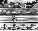 Figure 1. a) 360 degree panoramic photograph with characteristic distortion; b)
partial peripheral photograph of automobile tire surface; c) typical photofinish
photograph where print is line as a function of time; d) moving strip camera
sees subjects head-on and thus building sides are not visible.
Figure 1. a) 360 degree panoramic photograph with characteristic distortion; b)
partial peripheral photograph of automobile tire surface; c) typical photofinish
photograph where print is line as a function of time; d) moving strip camera
sees subjects head-on and thus building sides are not visible.
2. PERIPHERAL PHOTOGRAPHY
2.1 Development of the camera
As stated above, with standard strip cameras peripheral reproductions of
subjects of irregular diameter can not be produced without distortion because
the film can only match one particular image velocity at a time. For distortion
free records of these subjects the film must be able to move at various
velocities simultaneously, moving different amounts of film in equal time
increments.
A special case of a subject of varying diameters is a one whose diameter changes
in straight linear fashion. The development of the present camera is a direct
result of a request for a photographic peripheral record of a subject which had
just such a shape. In brief, the subject had a conical, rather than a
cylindrical, shape.
To recap then, while the surface velocity of a rotating cylinder is uniform and
thus its image velocity can be matched everywhere by a strip of film moving
behind the slit of the camera, the surface velocity of a rotating cone varies,
leading to various image velocities at the slit which can not be matched by the
film in a standard strip camera except at one point along the slit. In order to
cope with such a conical subject what is needed is either some optical technique
which can nullify differences in subject surface velocity or the development of
a peripheral camera capable of moving the film at a different velocity at one
end of the slit as contrasted to that at the other end. While a variety of
optical compensation methods were tried in order to equalize the image velocity
from subject areas moving at unequal velocities, none succeeded in establishing
a 1:1 image to film velocity relationship when the subject was conical in
nature. The methods which were attempted dealt with rotating the subject about a
tilted axis and with using the tilts of a moveable front and rear standard to
attempt to introduce differential magnification to compensate for the change in
subject circumference.
Eventually, it was a modification of the camera itself that resulted in the
development of a peripheral camera which could deal effectively with conical
subjects. It neatly solved the problem of differential image velocity along the
slit by moving the film in a circular, rather than linear, fashion, as is the
practice in all other "strip" cameras.
The basis for the design was the realization that on a turntable the surface
velocity is a function of the distance from the center of rotation. When a slit
is extended from the center of a turntable, a piece of film attached to the
turntable moves past this slit at increasing velocities with increasing distance
from the turntable's center. At a later date I made another connection with an
existing imaging system when I noticed that the manner in which a conventional
strip peripheral camera delivers undistorted records of cylindrical objects is
similar to the operation of a printing press. Here, a cylinder with information
on it's surface, transfers onto the support a series of perfect rectangles. That
is, the length of the transfered images per revolution of the impression
cylinder is the same at one end as at the other since the circumference of the
original cylinder is also uniform from one end to the other.
When one tries the same procedure with a conical subject by rolling it along a
surface, it becomes obvious that the surface which is generated is a circular
one. If the cone has an apex, then the apex will be located at the center of the
circle. The number of degrees out of a complete circle which the cone describes
during one revolution is a function of the steepness of the angle of it's side.
The steeper the angle, or more pointy the cone, the smaller part of a complete
circle which will be produced by making the cone complete one revolution. If it
is so steep that it is, in fact, a cylinder, then the length of the image along
the circle will be reduced to the width of a single line. In the case that the
cone is so flat that it is actually a flat circle, then the transfered record
will also be a full 360 degree circle. These conditions are obviously extremes
but it helps to think of these extremes to relate them to standard strip cameras
and to appreciate how these systems work.
Anyway, once I realized the operating principle of a camera which could
transport the film past a slit at various velocities, it took me very little
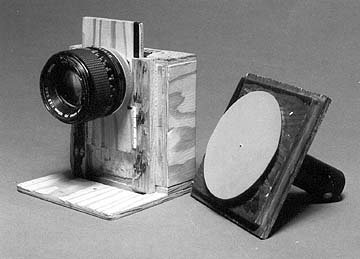
time to build a prototype model. It is shown in Figure 2. The camera was
designed to accept 4" diameter discs of film cut from regular sheet film. These
discs were held on the surface of the rotating circular film holder by means of
two-sided adhesive tape. The rotation rate of the film holder could be varied by
changing the voltage to the DC gearhead motor to which it was directly attached.
There was provision built into the camera lens mount to allow it to move along
the length of the slit so that an image could be formed at any given distance
less than 50mm away from the center of the film disc. Movement of the lens along
the slit, or radius of the film disc, is necessary because the lens position
needs to be adjusted depending on the characteristics of the cone being
photographed. Also, this capability allows the choice of the largest possible
magnification for a given situation. This ensures that the sharpness and
grainlessness of the records is as great as possible since the peripheral images
could always be made as large as the limits of the 4" diameter film disc would
allow for a given application.
 Figure 2. Strip camera with adjustable lens positioning track and variable
rotation rate film stage driven by DC gearhead motor attached to it through
camera back.
Figure 2. Strip camera with adjustable lens positioning track and variable
rotation rate film stage driven by DC gearhead motor attached to it through
camera back.
2.2 Setting up for peripheral photography of cones
The operational features of the camera permit it to effectively deal with
conical subjects of a wide variety of steepness to their sides. To set up for
operation the characteristics of the subject cone are first determined. These
include the measurement of the inside angle of the side at the base of the cone,
the circumference of the base of the cone and the length of the side.
Knowledge of the inside side angle allows one to compute the part of the
circular film in degrees which will be taken up by the image of the cone's
surface, A:
A = 360 degrees x cos inside angle
The inside side angle also determines time relationship between one revolution
of the subject R(s) and one revolution of the film bearing turntable, R(f).
R(s) = R(f) x cos inside angle
Under normal conditions, this means that if the time for one revolution of the
film disc is fixed, the time for one revolution of the subject will be a
fraction of the time for one revolution of the film and a number of peripheral
records can be produced on a single sheet of film.
The location of the image of the subject along the radius of the film bearing
turntable, or along the shutter slit, determines the operating magnification of
the camera. It is advantageous to operate at the maximum possible magnification
to minimize graininess. Once the magnification is known, then the camera
position is adjusted to make the image formed by the lens the right size for
proper reproduction.
I have found that the following procedure is convenient for setting up the
camera. First, the distance from center the base of the cone will be placed at
needs to be decided. To work at the maximum magnification, the base of the image
of the subject must be placed at the largest possible distance from center of
the film disc. In the camera described here the maximum useful distance from the
center is about 45 mm.
The operating magnification, M, is determined by finding the required image base
circumference, C(i), and dividing by the base circumference of the real cone,
C(c). Image base circumference, C(i), is found by mutiplying the circumference
of the circle of which the base of the image is a part of times the cosine of
the inside angle of the cone. Thus,
M = C(i) -:- C(c)
Alternately, M can also be found by dividing the circumference of the film disc,
C(f), along the circle on which the base of the image will be placed, by the
circumference of the circle of which the base of the subject cone is a part of,
C(s).
M = C(f) -:- C(s)
The denominator of the fraction above, C(s(, is given by dividing subject base
circumference by the cosine of the inside angle.The magnification, M, determines
what the image height of the cone's known side must be at the film plane when
the base of the image of the cone is placed on the circle of chosen radius.
Given a particular lens focal length, the camera distance is then adjusted so
that with the base of the cone located at the chosen distance from the center of
the film, the length of the image of the side of the cone, I, along the slit,
with S being the length of the real cone's side, is:
I = M x S
For distortion free reproduction, the optical axis of the camera must be
adjusted so that it is perpendicular to the surface of the cone. The film, then,
is parallel to the angled side of the cone. Then, the camera should be adjusted
in elevation so that the rotation axis of the film is aimed at the center of the
side of the subject. Small departures from this location are tolerable. With the
camera at the proper distance for the required magnification, the distance of
the lens axis from the center of rotation of the film must be adjusted to place
the base of the image of the subject at the desired radius. If the subject cone
has an apex, then this should now fall at the center of rotation of the film.
For this to happen the lens must have sufficient covering power. If the subject
is a truncated cone, then the point in space where the virtual apex is located
must be placed at the center of rotation of the film. If the image of the side
of the cone which the lens forms along the slit does not cover from the base to
the apex of the cone, the result will be an unexposed band around the center of
the image.
The exposure time, ET, is basically the length of time it takes a given point on
the film to pass by the open slit. Since in this camera the slit is cut so that
it is wedge shaped, the exposure time along the slit does not vary even though
the film is traveling more slowly towards the center of the film disc than along
the edges. Exposure time in seconds, ET, is determined by the angular size of
the slit, SW (deg.), and the rotation rate of the film disc, R deg./sec, as
follows:
ET = SW(deg.) -:- R deg./sec.
Once the exposure time is determined, the aperture is set so that with the film
loaded in the camera and the available lighting level a proper exposure will
result.
The present camera can achieve film rotation rates of about 10 degrees per
second, and the slit is about 1 degree in size so that minimum exposure times
are in the order of 1/10 th of a second. The film can be slowed down to about 1
degree per second by simply decreasing the voltage to the DC gearhead motor. The
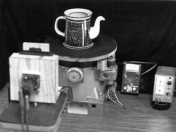
camera is shown in a typical application in Figure 3. A peripheral negative and
enlargment generated by the camera are shown in Figure 4 and 5 respectively.
 |
 |
 |
| Figure 3. Peripheral photograph made of a conical teapot placed on a turntable.
|
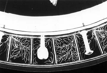
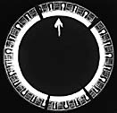
Figure 4. Negative from camera showing multiple reproductions around circular
negative.
|
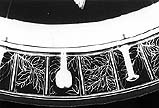
Figure 5. Detail, note handle and spout rendition.
|
3. CONICAL PANORAMIC PHOTOGRAPHY
3.1 Development of conical panoramic application
Once the camera served its function of making the desired distortion free
peripheral record of a conical subject, I investigated applications in panoramic
photography.
By way of introduction to this application of the present camera it may be
appropriate to state that it is a well established operational fact among
panoramic photographers that panoramic cameras must rotate about a vertical axis
unless one is willing to accept horizon lines that wander up and down along the
panoramic image. A variation on this theme is one in which photographers have
tilted their cameras down while still keeping the axis of rotation vertical so
that the horizon line effectively remains level. Attachments are available,
particularly for the Cirkut-type cameras, which allow the cameras to point up,
or down, while still keeping the axis of rotation of the camera vertical. The
idea is that if one can raise or lower the angle of view and still keeping the
axis of rotation vertical, one can lower or raise the horizon line while still
keeping it parallel to the film edges along the panorama.
The difficulty which photographers who have investigated the use of these camera
tilting attachments have found is that their photographs are no longer sharp
from top to bottom, although indeed the horizon line is parallel to the sides of
the film from end to end. The reason for this lack of sharpness is that in this
mode the slit and film plane in their basic strip panoramic camera no longer
describes a cylindrical path but rather a conical one. The result is that while
the camera views equiangular rates of change along the slit these do not
encompass equidistant displacements in the subject. In fact, if the camera could
be tilted so far down or up that the point about which the camera rotates were
included on the film, this point would be standing still. Therefore, the conical
surface which the slit of the tilted camera describes results in uneven image
velocity along the slit.
Yet, as discussed earlier, the film, moving in linear fashion, can only produce
a cylindrical record since the film velocity is constant along the slit of the
camera. To solve this particular problem and to produce conical panoramic
images, the camera which I designed and constructed to make conical peripheral
photographs can itself be mounted on a rotating turntable to produce conical
panoramic photographs. See Fig. 6.
3.2 Setting up for conical panoramic photography
The operating procedures for using this camera in the panoramic mode depend on
the lens which will be used and the dimensions and characteristics of the cone
which one wishes to make. Once the lens focal length which will be used is
chosen and the desired side angle of the cone is fixed, these two parameters
determine where the lens must be placed with respect to the center of the film
disc and the relationship between the time for one revolution of the film disc
in relationship to the time for one revolution of the camera.
The inside side angle which is chosen must be the angle that the film disc
surface must maintain with respect to the horizontal as the camera rotates about
a vertical axis. The camera may be pointed upward or downward. In the former
case the slit must be located above the axis of rotation of the film disc, while
in the second case the slit must be located below the axis. Alternately, the
camera needs to be merely inverted when it is pointed downwards. The reason for
the location of the slit above or below the disc rotation axis is that the
center of the disc must record those areas of the subject which are nearest the
apex of the cone which the rotating camera is describing. In both instances the
film disc must be turned in such a direction that it matches the direction in
which the image moves with respect to the slit in the camera.
The location of the lens from the center of rotation of the film disc, D(L), is
a function of the lens focal length, F(L), and the side angle. More precisely,
the rear nodal point of the lens must always be located directly above or below
the center of rotation of the film disc. This displacement of the lens axis from
the center of the disc is a function of the tangent of the inside angle and the
lens focal length:
D(L) = F(L) x tangent inside angle
This relationship fixes that the lens position, when the side angle is 0
degrees, equaling the inside angle of a flat "cone", must be such that the lens
axis is directly above the center of rotation of the disc. In this case the
camera is pointed straight up and only half of the image circle produced by the
lens falls on the slit. Conversely, when the inside angle approaches 90 degrees,
the lens must be located at a great distance from the center of the film disc in
order for it to be above the center of the disc. At a side angle of 90 degrees
the lens will be infinitely far away. At such a distance, as far as the lens is
concerned, the film will move in linear fashion rather than circular fashion. At
this extreme the length of film required to cover a 360 degree panorama will be
equal to 2pi times the lens focal length. In fact, this extreme is a special
case of the "conical" camera, and is exemplified by the traditional cirkut type
panoramic camera!
The above factors determine whether the film disc available in a given camera is
large enough to accomodate the chosen lens at a desired side angle. For any
given diameter film disc, use of long focal length lenses will restrict the
camera to the production of shallow cones, while short focal length lenses will
allow cones of steep inside angle although at reduced image sizes. The four inch
diameter disc which this camera uses can make cones of up to about 65-70 degrees
side angle (average for lamp shade use) with lens focal lengths of about 20mm.
Unlike cylindrical panoramic cameras, where the lens can be raised or lowered to
alter the position of the horizon line, in conical cameras, the placement of the
lens at other than the one position determined from the factors named above will
produce blurring along the height of the panorama or radius of the circle.
The relationship between the time for the film disc making one revolution, R(f(,
and the time taken by the camera to scan 360 degrees, R(c(, are given by:
R(c) = R(f) x cos side angle
This means that under normal conditions, more than one 360 degree panorama can
be included on one disc of film. In fact, when the inside angle of the cone is
60 degrees, exactly two 360 panoramas can be recorded because the cosine of this angle
is .5.
The angular rotation rate of the film determines the exposure time for a given
angular slit width. Exposure time is determined through exactly the same
procedures described above when they were applied to the making of peripheral
photographs. Figures 6 and 7 illustrate the general set-up of the camera for
making a conical panoramic record and the resulting negative.
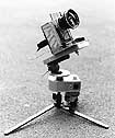
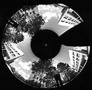
Figure 6. (on right) Camera mounted on motorized, tiltable, tripod head.
Figure 7. (on left) Two full 360 degree panoramas are recorded on less than 360 of film.
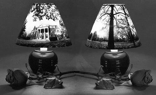
3.3 Applications for conical panoramic images
The images produced this way could find direct application in transfer to such
items as lampshades, see Figure 8, novelty hats, and decorative purposes for any
number of items which have a more or less conical shape. Presently, adaptation
of standard images to the surface of objects of conical section requires digital
analysis and manipulation which is not an impossible task but not readily
available to photographers used to more standard recording techniques.
A further application of the present camera is that with a slight loss in
sharpness it could be used to distort conventional cylindrical panoramic or
other images so that they could be bent into, or adapted to fit, conical shapes.
This loss in sharpness is associated with the mismatch in image vs. film
velocities resulting from the alteration of the aspect ratio of the original as
the conical image is made. The blurring effects of this differential movement of
the image with respect to the film can be minimized by making the exposing slit
very narrow, thus limiting the exposure time during which blurring can affect
the recorded image.
4. CONCLUSION
In summary, the development and operating characteristics of a camera suitable
for making distortion free peripheral reproductions of the surface detail
appearing on subjects of conical shape have been described. The application of
the camera for making panoramic photographs and their subsequent display as
conical objects has also been reported. When the operating limits of the
circularly moving film camera design, as exemplified by the present camera, were
investigated it was established that strip cameras in which the film moves in
linear fashion are special cases of the design and operating principles of the
circularly moving film approach described above.
While the number of instances where this camera would be found useful is
probably quite low, significant improvement over the use of standard strip
cameras for peripheral photography of objects with a tapered shape has been
demonstrated. Further, when applied to panoramic work, this camera is able to
produce photographs which are suitable for a variety of utilitarian purposes
without additional manipulation.
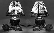
Figure 8. The George Eastman House and adjacent grounds made into a 360 degree
panoramic conical lampshade.
References for additional information:
Research Engineers Corp. of Great Britain used to manufacture an attachment for
4x5 view cameras which allowed the user to produce peripheral photographs
onto sheet film. Along with the attachment they also sold a precision
turntable and centering device. The Charles Hulcher Co. and Robot Inc.
both offer 35mm image motion or strip cameras which are quite suitable for
peripheral photographs when coupled with user supplied turntables. An
advantage of the Hulcher camera is that it can also easily make 360 degree
wide angle or panoramic photographs. The Globuscope panoramic camera can
also be used for peripheral photography although its usefulness is limited
due to the high rates of film transport it is designed to deliver. The
Sugawara Co. offers the Film Streak V, an attachment for standard 35mm
cameras to allow them fairly smooth film transport in the rewind mode as
described above.
With the development of linear array digital scanning camera backs the
possibilities of peripheral photography are being re-invented by a group of
people who suddenlty realize the potential for imaging subjects in the
scanning, rahter than instnataneous, mode. Something that panoramic and
peripheral and photofinish and aerial photographers using strip cameras have
known since at least the start of the 20th century!
Should you have a need for precision peripheral photography services,
these are also not readily available. The author of this paper is in a
position to help with a limited number of projects through the cooperation
of the Imaging and Photographic Technology department at the Rochester
Institute of Technology. He welcomes inquiries regarding this process from
individuals desiring help with specific problems they may have as they
become involved in peripheral recording techniques.
Andrew Davidhazy is a Professor in the Imaging
and Photographic Technology department of the College of Graphic Arts and
Photography at the Rochester Institute of Technology. His teaching centers
on instruction related to the use of photography a a tool of measurement
and visualization for researchers, scientists, engineers and technicians.
Among the topics included in his laboratory's activities are infrared and
ultraviolet photography, high speed and time lapse, panoramic and
peripheral photography, low level aerial photography and close range
photogrammetry, thermography, close up and long range photography,
photographic documentation, etc..
PERTINENT REFERENCE MATERIAL
Nicholas Helmut has been doing rollout (peripheral) photographs of
Mayan vases and has several examples of his work on the web. Take a peek at:
Maya Vases and his brief
history of rollout
photography page.
Burns, C., and Watson, K.O.,"A Camera for Photographing the Surface of
Cylindrical Specimens", The Photographic Journal, Vol. 101 (Royal
Photographic Society), (September 1961), pp 273-277.
Delius, Peggy, "The Shell Periphery Camera", British Journal of
Photography, (October 13, 1961), pp. 598-604, 610.
Fox, F., "All Around Eye", Shell Magazine, (August 1961) pp. 219-221.
Luck, H. R.,"Piston Photographing Machine in Fuel and Lubrication
Research", Industrial Photography Magazine,(July 1956) pp. 22-23 ff..
Luck, H. R.,"Photographing Cylindrical Objects", Photographic Society of
America Journal, (February, 1946) pp 61-68.
Wise, Lindsay,"Peripheral Photographs for the Small Industrial Photography
Department", British Journal of Photography (May 1966) pp. 384-389.
Noble, Joseph V.,The Techniques of Painted Attic Pottery, Watson-Guptill
Pub., New York, 1965, p. 101.
Illustrated London News, August 31, 1963, pp 320-321.
Invention of peripheral photography may be attributed to Cyril Smith or to
Arthur Murray Smith under the name of "cyclographs"...maybe.
On the other hand, another account has it that Arthur Hamilton Smith,
Keeper of the Greek and Roman Antiquities at the British Museum designed a
peripheral instrument with the assistance of the optical firm of Ross for
the photography of ancient pottery. This was reported in the Journal of
the Royal Photographic Society volume 19, May, 1895.
Andrew Oliver, Jr., Associate Curator, Greek and Roman Art, The
Metropolitan Museum of Art, New York, NY 10028 may know something of
application and/or history of technique.
Raymond Davis designed a camera for photographing short lengths of
corroded pipe and described it for the American Bureau of Standards No.517,
Vol. 20, December 1925.
Emil D'Isoz of the Budapest Museum seems to have developed a camera also.
The British Iron and Steel Research Association made the Evolute Camera
around the early 1950's or so.
The Shell Development Co. reported in the S.A.E. Journal a camera for the
photography of pistons in Vol. 51, No. 2, February 1943.
ADDITIONAL RELATED MATERIAL:
Makers of Peripheral Cameras:
L.F. Deardorff & Sons, Inc. 11 S. Des Plaines St., Chicago, IL 60606
Research Engineers, Ltd., Orsamn Road., London, ENGLAND N1 5RD
Charles Hulcher Inc., "G" Street, Hampton, VA
Hermann Seitz, Switzerland
articles, etc:
Kodak Job Sheet Number 8, Peripheral Photography, Kodak Pamphlet No. P-100-8
Published by the Professional, Commercial and Indistrial Photography Division
of the Eastman Kodak Company, 9-67
Davis, Raymond, "A special camera for photographing cylindrical surfaces"
Scientific Papers Numer 517, Volume 20, Dec 1925, National Bureau of Standards,
Washington, DC
Photography Handbook Number 2, p. 102, 1938. "Flat pictures of round objects"
published by Fawcett Publications, Greenwich, CT
"A Piston 'Strip' machine", S.A.E. Journal, Vol. 51, Number 2, February 1943
D'Isoz, Emil, Budapest Museum
British Iron and Steel Research Association - "The Evolute Camera"
Hamilton-Smith, Arthur, "The Cyclograph", Journal of the Royal Photographic
Society, Volume XIX, May 1985.
related articles below by Davidhazy, A.
"How I Broke the Reality Barrier", POPULAR PHOTOGRAPHY, October 1970, volume
67, number 4, pp.75-77.
"Looking at Life Through a Slit", MILWAUKEE JOURNAL,June 27, 1971.
"Simplified Streak/Strip and Scanning Photographic Systems", in the
PROCEEDINGS OF THE 15th INTERNATIONAL HIGH SPEED PHOTOGRAPHY CONGRESS, L.
Endelmann, editor. Published by SPIE, the International Society for Optical
Engineering, volume 348, pp. 148-153, 1983.
"Peripheral Photography", February 1986 issue of CERAMICS MONTHLY magazine,
Vol. 34, number 2, pages 48-50.
"Peripheral Photography: Shooting full circle", in the January 1987 issue of
INDUSTRIAL PHOTOGRAPHY magazine, vol 36, number 1, pp. 28-31.
"Principles of Peripheral Photography", Fall 1988 issue of the POLAROID
PhotoEducation NEWSLETTER FOR PHOTOGRAPHIC EDUCATORS, pp 6-8.
"Forenklade system for Svep/spalt och scanningfotografering", pp 16-21 of
#2/1992 issue of the Tidskrift for MEDICINSK OCH TEKNISK FOTOGRAFI".
"Camera for Conical Peripheral and Panoramic Photography" in the Conference on
Current Developments in Optical Engineering and Commercial Optics, Part of
33rd Annual SPIE Conference held in San Diego, CA in 1989. Published in the
proceedings of this conference.
The following patents may have related information concerning the peripheral
reproduction of conical subjects: United States Patent Number
2,617,337 Snyder Reproduction of Conical Forms Jan. 19, 1949
1,001,549 Mertens Aug. 22, 1911
1,176,384 Lotka Mar. 16, 1916
1,456,954 Von Lucken May 29, 1923
1,738,095 Carleton Dec. 3, 1929
1,844,162 Hirsch Feb. 9, 1932
1,904,672 Berthon Apr. 18, 1933
2,066,782 Heymer Jan. 5, 1937
2,286,880 Weber Jun. 16, 1942
2,288,352 Henderson Jun. 30, 1942
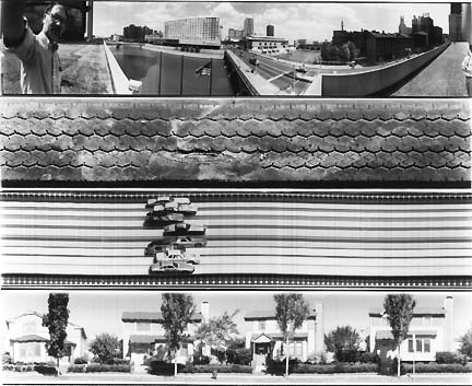 Figure 1. a) 360 degree panoramic photograph with characteristic distortion; b)
partial peripheral photograph of automobile tire surface; c) typical photofinish
photograph where print is line as a function of time; d) moving strip camera
sees subjects head-on and thus building sides are not visible.
Figure 1. a) 360 degree panoramic photograph with characteristic distortion; b)
partial peripheral photograph of automobile tire surface; c) typical photofinish
photograph where print is line as a function of time; d) moving strip camera
sees subjects head-on and thus building sides are not visible.