|
More Complex Photogrammetry Projects Andrew Davidhazy Imaging and Photographic Technology Rochester Institute of Technology If you are looking for
projects that are sure to fire up your imagination as well as exercising your
intellectual abilities I would like to suggest that you consider dabbling in
basic photogrammetry. This is the science of making measurements from images.
Typically these measurements might involve determination area, of elevation
above a certain reference mark or distance from the camera or subject volume The projects described
below would be suitable for anyone with some interest in basic physics,
mathematics and photography. I fact I believe they are suitable for anyone who wishes
to find a technical application for their cameras. The premise of this
presentation is that while many can identify with photography as a way of
making family records and recognize it as an aesthetic outlet for their
creativity, photography is often only perceived in terms of its historic or
creative potential. Less obvious is the fact that photography can also serve as
a vehicle with which to dabble in applied mathematics. In this case we will take
liberal exception with absolute accuracy and will concentrate more on the
fundamental principles at work. What follows is a
description of how simple photography based exercises can be used to learn a
fairly sophisticated application of trigonometry, much as the shadow method of
determining the height of a flagpole is often used even at the elementary
school level to introduce students to trigonometric principles. Photogrammetry is a
branch of scientific photography concerned with the technical application or
imaging devices, such a simple cameras, for the express purpose of generating
images from which measurements of subject characteristics will be made. Briefly, in aerial and
terrestrial photogrammetry a pair of photographs is made of a subject from two
different but well established viewpoints. This pair of photographs is commonly
referred to as a "stereo pair". Once developed or digitally recorded and
then printed, these are placed side by side and carefully positioned so that
measurements made from the pair can then be interpreted as subject locations
measured from the camera positions based on elementary trigonometric
principles. A major drawback of the
technique when attempted in simplified fashion, is that it is quite difficult
to position the two prints properly. This results in substantial errors
creeping into the measurements that are subsequently made from the photographs,
I would like to suggest,
however, that this difficulty can be overcome and that one can effectively
become acquainted with principles of trigonometry, photography and
photogrammetry, through the use one's own personal cameras and reliance on
readily available 1-hour processing services. Since your own personal
cameras are used the project becomes even more interesting. In addition to
using your own camera you could also try some manual skills by building your
own "stereo bar", test its performance and then use it to measure
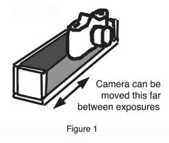
unknown distances. STEREO BAR
DETERMINE THE DISTANCE
FROM THE CAMERA TO AN OBJECT Although for this first
application a stereo-bar is not absolutely needed it's use will make it
somewhat easier to complete the project. One simply needs to line up the back
of the camera with a straight edge or surface and move the camera from one
place to the other. The edge of a desk, a convenient wall, or even a windowpane
against which the lens is firmly pressed will all work adequately. One only
needs to remember to move the camera along a level surface without twisting it. Since one major problem
associated with making measurements from stereo pairs arises from the
difficulty of lining up the two separate images, the method suggested here is
based on the principle of making the two successive exposures, one from each of
two independent locations or from two ends of the stereo bar, onto the same
piece of film! You might think that if you do this the resulting image would he
a complete mass but this is not necessarily the case. Of course, the camera
used for this project should therefore have a provision for making multiple
exposures on the same piece of film. Many simple box cameras and some modern 35
mm cameras allow this but it may take some reading through the instruction
manual to find out the mechanism to accomplish it. Alternatively, the
slowest possible film could be used, the shutter set on "B", locked
in the open position, the lens set to its smallest aperture and the exposure
controlled by a card quickly removed from and replaced in front of the lens.
After the two exposures have been made this way the shutter is again closed. Since only one
"double exposure" will be made on the film no major adjustment of
exposure needs to be made under most conditions. Use the same aperture/shutter
speed for both of the sequential exposures. In principle, objects
located very far away from the camera Will hardly move across the film as the
camera is moved from one side of the stereo-bar to the other, while subjects
located at closer distances from the camera will move considerably. The degree
of movement of the image of a given subject will depend on the lens focal
length, the subject distances and distance between the two photographs. In fact, as shown later,
the process can be used to determine the focal length of the camera lens if
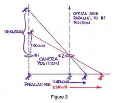
there is an object in the scene whose distance from the camera is known. The operating principle
here is that once you know that a given object distance will cause a particular
separation, known as "parallax", unknown distances can by determined
by an inverse relationship that exists between the separation between these
other images and the distance from the camera to them. In other words, the
Object Distance to an object at an unknown distance can be determined by
multiplying the distance of an object at a known distance by its Parallax and
dividing by the Parallax for the object at an unknown distance.
Known Object Distance
x its Parallax Unknown
Object Distance =
----------------------------------------------------
Parallax for Object at Unknown Distance
To amplify on this
further, as shown in Figure 2, an image
whose parallax is one half the magnitude of that of an object whose distance is
known will be caused by an object that is twice as far as the object whose
distance is known. The advantage of this method is that for most practical
purposes the measurements are independent of camera, lens focal length,
distance between the two photographs and the size of the enlargements that you
happen to work with. It is suggested that you use the same measurement units
throughout. It is true that the
precision of the measurements is increased by making the distance between the
two photographs as large as possible while still including the
"standard" object as well as the unknown object in both photographs.
In addition it is helpful to enlarge the original negatives as much as
possible. Even though 4x6 inch
color prints are useable, enlargements to 8x10 inches make the measurement
process based on standard rulers more accurate. Another way to increase
accuracy is to enlarge the negative with a slide projector to truly large
proportions. Although you might think that you must use slide or transparency
film to place your images in a slide projector, B&W or color negatives can be mounted
in a slide mount and projected to large sizes with standard Carousel
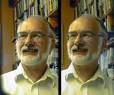
projectors. You could even experiment
with making the two exposures on color film but using a red an a green or blue
filter for the second. If a slide made this way is projected on a screen
through a red filter, the image formed by the green filter becomes mostly
visible and the green filter will make the red image visible. This makes it
easy to check on the difference between the left and the right hand views. Based on the procedure
described above, namely making sure to include an object at a known distance in
each of two photographs taken from different locations, object distances to
unreachable subjects can be quite simply determined. DETERMINE THE FOCAL
LENGTH OF A CAMERA LENS
The principle here is
that far objects taken from two different points of view located near each
other will be reproduced almost on the same location on the film if the film
does not move between exposures. Near objects, on the other hand, will move an
appreciable and measurable amount. To begin with we will assume that the film
does not accidentally move between exposures and that the camera, as it is
moved from one side to the other of the simple stereo-bar, points exactly in
the same direction as it did when the first one photograph was taken. To determine the focal
length of the camera lens based on an enlarged print, again, first notice that
far objects superimpose on each other on the print. Then measure the distance
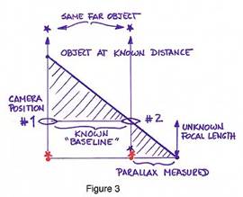
between the images of the near object. By simple visual
examination of the set-up it is evident that similar triangles are being formed
in front of the camera and within the camera. This is shown in Figure 3. To determine the focal length of the
camera lens multiply the known Object Distance by the Parallax of this Object
and divide by the distance between the two camera positions, known as the
Baseline.
Known Object Distance X its Parallax
Focal Length = --------------------------------------------------
Baseline Strictly speaking this
method is applicable for "contact prints" and you typically wi11 be
working with enlargements. The actual focal length of the camera lens you use
can be determined by taking this ÒartificialÓ focal length that you determine
for the enlargement you happen to be working with and dividing it by the number
of times that your print is bigger than the original negative. For example, if
you are making 8X1O enlargements of 35 mm negatives, the focal length you
determine for that print size needs to he divided by about 8 to arrive at the
actual focal length of the camera lens. To find out the actual
magnification of the negative marks could be scribed on the negative, or slide,
a known distance apart, let's say 20mm. Dividing the distance between these
same marks on the enlargement by 20 mm gives the true magnification of the
enlargement. It is possible that the
camera did not aim exactly in the same direction both times or that the film
moved slightly, or possibly significantly, between the two exposures. If this
happens one simply needs to subtract from the parallax measured for the near
object the distance between the locations of the images of the far object and
this result used as described above. While movements of the film can be
compensated for this way, large changes in camera pointing direction can not be
easily corrected and dealing with these errors is beyond the scope of this introductory
project. DETERMINE OBJECT
DISTANCES BASED ON THE STEREO-BAR Finally, once an accurate
knowledge of the camera focal length is obtained, the camera and stereo-bar
combination can be used to make measurements in locations where all object distances are unknown. Referring again to Figure 3, the measurements are based on a
knowledge of the camera lens focal length and the baseline as follows: the
Object Distance is equal to the established Focal Length times the Baseline and
divided by the Parallax of the image of the object question.
Lens Focal Length X Baseline
Object Distance = ---------------------------------------------------
Parallax of Object at Unknown Distance Again, if you are working
with an enlargement, the actual focal length of the camera lens needs to first
be multiplied by the number of times that the enlargement is bigger than the
negative in the camera and then this new Focal Length is used for Object
Distance determination. For example, if you are working from 8X10 enlargements
your camera focal length needs to first be multiplied by about 8. Photography is a powerful
means for creative artistic expression. Hopefully this project will be of use
to you as you develop an appreciation of its added potential as a useful
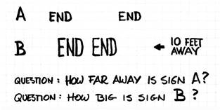
engineering, scientific and technical tool. Finally, I have a small
"quiz" I would like to pose and ask you to answer the questions asked. Since
actual units are not given you should give your answer in relative terms using
sign A or sign B as the reference object size.
Answer: Sign A is
½ the distance from the camera that B is (or 5 feet) because its
parallax is twice as large as that of sign B. Sign B is 4 times larger than A. The reason is that if both signs were the same size
A should B twice as large as B but A is in fact only ½ Bs size here even
though twice as near and therefore it must be ¼ the size of B. If I may be of assistance
to you as you give this project a chance please feel free to contact me at the
Imaging and Photographic Technology department of the School of Photographic
Arts and Sciences at the Rochester Institute of Technology, 70 Lomb Memorial
Drive, Rochester, NY 14623. My fax number is 585-475-7750 and you can also
reach me by e-mail at andpph@rit.edu
|