|
Basic Photogrammetry Techniques Imaging and Photographic Technology School of Photographic Arts and Sciences Rochester Institute of Technology
Measuring Heights of Displaced Objects The exaggerated displacement of tall objects pictured near
the edges of large- scale, vertical
photographs sometimes permits accurate measurement of object heights on single
prints. This specialized technique of height evaluation is feasible provided
that: a. The principal point can be accepted as the nadir
position. b. The flight altitude above the base of the object can be
precisely determined. c. Both the top and base of the object are clearly visible
and the top is directly above the
bottom. d. The degree of image displacement is great enough to be
accurately measured with
available equipment, e.g., an engineer's scale.
When all these conditions can be met, object heights may be
determined by this relationship:
D x A Height (in feet) = ------------------
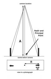
R Where D is the length of the displaced image in inches. A is
the altitude above the base of the object in feet. R is the radial distance from the nadir to the top of the
displaced image, in inches. The NADIR point on a vertical aerial photograph is located where the optical axis (or roughly the
center) of a photograph is. This can be approximately found by drawing diagonal
lines from the corners of the photo and where they intersect that is the
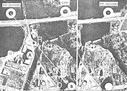
middle. Practical application of this method can be illustrated by
use of the figures below. These photographs were taken from a flight altitude
of 3,000 feet with a camera focal length of 6 inches. Radial measurements from
the assumed nadir position to tanks" A" and "B" may be
substituted in the preceding formula: Height (Tank "A") = 0.18" x 3,000' / 2. 34" = 231 feet Height (Tank "B") = 0.38" x 3,000' / 5.00" = 228 feet Thus both tanks are about the same height, and the
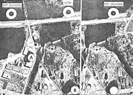
measurement of tank "B" could be re-checked on the right-hand
photograph: Height (Tank "B") = O. 30" x 3,000 / 3.84" = 234 feet In these examples, the three estimates of height show closer
agreement than may be obtained by casual measurement. In the last computation,
for instance, an error of only 0. 02-inch in the length of the displaced image
would have affected the final answer by 16 feet.
Determining the Size of Irregular Areas by Weight The total area of several irregularly shaped areas of the
same scale can be determined quite accurately by the following steps, Step 1. Weigh the photos on which the areas of interest are
pictured. Step 2. Cut out the irregularly shaped areas from the
photographs. Weigh the cut‑out
section very accurately. Step 3. Cut out an area of known size, and weigh it very
accurately. Step 4. Divide the weight of the representative area into
the weight of the cut‑out
sections of the area to be found. Step 5. As an accuracy check, add the weights found in Steps
2 and 3 above. Their total should equal the weight found in Step 1. This method requires that an extremely accurate scale (for
measurement of weight) be available, and that ground elevations of both the
irregularly shaped and the representative areas all be the same, since photo
scale (and area) changes with the altitude of the terrain. This method is very
good for measurement of water areas, because the surface areas are level and
usually relatively close to the same elevation. Application: To find
the size of an area which has been flooded, for example, the following should
be done: 1. Cut out the flooded areas from the photos, and weigh
them. They are found to weigh 8,000 grams. 2. Cut out a representative area. An area of 640 acres (one
square mile, or one section) is selected, and found to weigh 800 grams. 3. Then 8000 g / 800 g = 10 and thus the total flooded area
is 10 sq mi Determining Graphically the Size of Irregular Areas
by Approximation The total area of irregularly shaped subject areas
reproduced in a photograph at the same scale can be determined graphically
quite accurately by the following steps: Step 1. On the print find the area of a known quadrangle
based on "ground truth" or some other method by which the scale of the
photograph can be determined. Step 2. Project this figure al over the image of the subject whose area needs to be
determined. Instead of drawing directly on the print you could draw on an
acetate overlay. Step 3. Count the number of whole quadrangles that can be
identified within the confines of the subject boundaries whose area needs to be
determined. Step 4. Estimate the total number of whole quadrangles that
would be made up by those that only partially fall within the boundaries of the
subject area. Step 4. Add the number of whole quadrangles to the area
comprised by the partial quadrangles. Step 6. Multiply the total number of quadrangles by the area
of the reference quadrangle. This is the approximate area of the subject of interest. Determining Subject Height from Shadows The calculation of object height from its shadow length
requires that: 1. The exact "sun" or sidereal time when the
photograph was taken be known. 2. The precise geographic location of the object be known. 3. A table of sun declinations at different times throughout
a four-year period be available. The table below is sufficiently accurate for
most calculations. The appropriate formula is: (H) ( 1) (tan solar altitude) h = -------------------------------------- f where h = height of the object H = altitude of the photo plane above the ground, l = length of the shadow f = focal length of the camera. The solar altitude in any location at any given time can be
obtained from various government agencies concerned with astronomy and time. It
can also be computed by using the following factors: 1. The sun's declination on the day of the photography (obtainable from table 1) (a) 2. The latitude of the area. (b) 3. The difference in longitude between the celestial meridian passing through the sun at the instant of exposure and the meridian of the area which is imaged. (c) When these qualities are known, the solar altitude can be
computed by the relation:
Solar altitude = sin x =
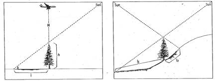
(cos a) (cos b) (cos c) + (sin a) (sin b) The relationship of shadow length and object height to the
altitude of the sun are obvious, as shown in Figure 1. It is equally obvious,
however, that this method may lead to serious errors if shadows do not fall on
level ground (or other flat surface). If the ground slopes down, shadows will
appear too long. If the ground slopes up, shadows will appear too short.
Shadows that can be seen falling water surface usually provide a very good
reference plane. Alternatively, if the sun's altitude above the horizon is
already known, a short cut method of determining the height of a vertical
subject above level ground can be found by referring to the figure below on the
left.
The height of vertical objects can be calculated accurately
from vertical photographs by measurements made from a photograph regardless of
its scale of reproduction simply based on shadow length if location, sun
altitude, camera focal length, and flying height are known. Use the following
formula already given above:
H l (tan a)
h = ----------------
f where h is the object height, H is the flight altitude above
the base of the subject, 1 is the shadow length, a is the altitude of the sun,
and f is the camera focal length, as shown on the left. As shown on the right,
however, shadows must fall on level ground. If the surface slopes down, shadows
will appear too long. If the surface slopes up, shadows will appear too short. These guidelines were copied from booklets and pamphlets whose origin I can't remember. All are over 30 years old. If they are your writing and you'd like me to delete them from here please let me know and the section will be eliminated ASAP. The bit on quadrangles and use as the basis for area measurement I made up "off the top of my head" and so look at it with suspicion. Happy measuring!! Andrew Davidhazy, andpph@rit.edu
|