Audio activated SCR sound synchronizer
Making photographs by activating a high speed flash in response to some sound has many applications in photography. Especially in the area of high speed photography. There are several commercial sound activated synchronizers on the market but this is intended to encourage photographers to make their own device. There is an approach based on using a standard cassette tape recorder activating an electronic switch known as a SCR and you can find instructions on how to do that at: http://people.rit.edu/andpph/text-cheap-sync.html However, if you are adventuresome and somewhat handy with electronic circuits and tools you may be interested in starting from "scratch" as they say. This can be done by replacing the tape recorder's function, which was to act as a sound detector and firing signal to an attached SCR, with a basic integrated circuit audio amplifier. The one chosen here is the LM386 audio amplifier and it was described by Forrest Mims in several of his circuit project books. Besides the 386 IC device you will need the SCR that it will activate. It is a BRY55 400 device but equivalent SCRs should work as well. In addition you need a microphone, a couple of capacitors (10 uF and 220 uF) and a resistor (2.2 Kohm), a 9v. battery clip plus some wire and some means for connecting the flash PC plug to the SCR's Anode and Cathode leads. This is usually accomplished by attaching a female PC socket to the output of the circuit but such sockets are hard to find. It is possible to buy a PC-to-PC extension cord and use the female half to connect to the SCR. If this is too expensive below you will find instructions on how to make an improvised PC socket. The original schematic for the synchronizer is shown at left below. At right is the slightly modified version which served as the basis for the synchronizer I made. I used a Radio Shack generic pre-etched and perforated board onto which I plugged in the several components and soldered in place. I chose to make the device so that it would not be super sensitive as that tends to fire anything connected to the SCR at sometimes inopportune times. The original schematic does include details on how to make the input to the 386 so that it is variable in sensitivity. Note that there are several leads that connect to a common ground or the minus input from the battery. This includes one side of the microphone input, pin 2 of the IC, pin 4 of the IC and the C or cathode of the SCR. 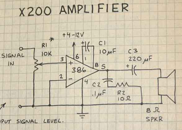 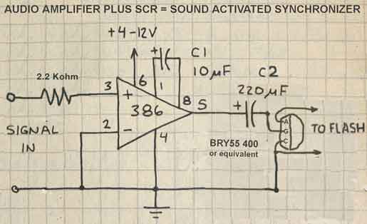 The final perfboard project, minus female PC connector is shown below. It will fire an electronic flash connected to it by way of the two upper leads at the sound of a clap of the hands from about 3 or 4 feet away from the microphone. Note that the output of the SCR needs to be connected to the input of the flash in a particular way. It is said to be "polarized". If the synchronizer fails to fire the flash with the leads connected one way try reversing their connection. The microphone that I use is one that was used for tape recorders. Described as a dynamic microphone I believe. 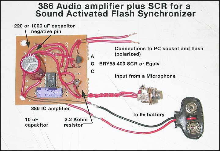 so there you have it! Please note that there are various things that ultimately determine whether the device you build will work as expected ...or not. If the one you make does not perform as expected I must mention my expertise in circuit troubleshooting is not extensive and I probably can not provide you with hints on how to make your synchronizer work. On the other hand if you are successful I would be pleased to hear of your success! Now for the improvised PC connection
As mentioned above, PC sockets are hard to get so I decided
to make my own. Visiting a hobby store I bought two lengths of bronze
tubing. One was 1/16 inch diameter and the other 1/8 inch outside
diameter. The thinner tube easily fitted withing the inner diameter of
the larger one and the hole in it was large enough to acomodate the pin
built into the centers of the male PC connectors.The 1/8 inch tube is, however, too large to accept the PC male connector and it has to be reduced by some means to 3 mm in outside diameter which is what the PC plugs are designed to fit ove. After removing a very thin layer of bronze from the larger tube I wrapped the smaller one with some tape (I used clear packaging tape but any flexible tape should work) until it was still able to be press fitted snugly into the opening in the larger tube. During this process of mating the two I periodically checked to make sure that there was no contact made between the walls of the two tubes by checking resistance with an Ohm meter. 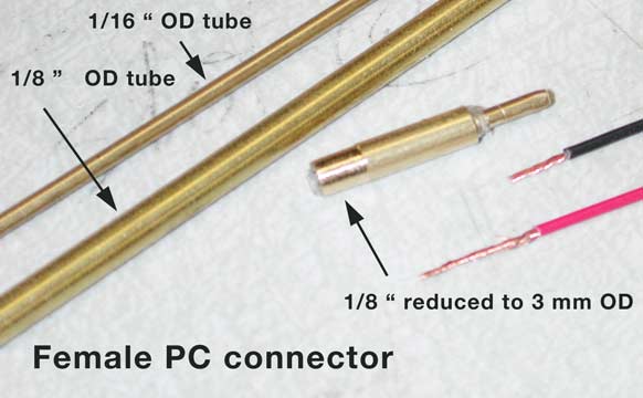 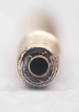 On the left are the parts prepared for final assembly and on the right a frontal view of the manner in which the smaller diameter tube fits into the larger one with insulating material between them. Ultimately you may want to cover the bottom part of the assembly in epoxy or similar material to protect the bare leads that connect the socket to the synchronizer. And below is the finished PC connector attached to the output of the SCR which is activated by the 386 IC audio amplifier driven by an attached microphone and ready to make action stopping photographs whenever a medium level sound is picked up by the microphone! 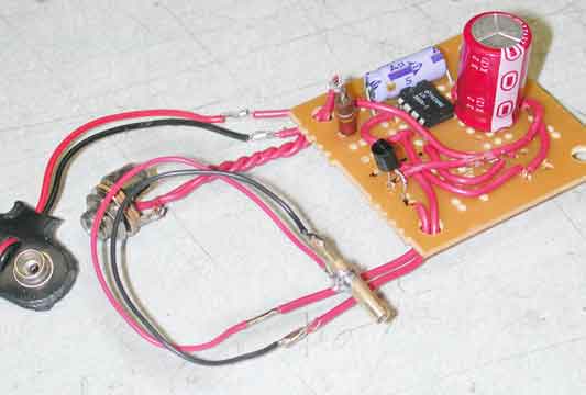 If you found any of this of
interest feel free to contact me at my address supplied below.
|