100 Hz flashing LED source for timing
applications
Andrew Davidhazy
Images for Science, Industry and Education
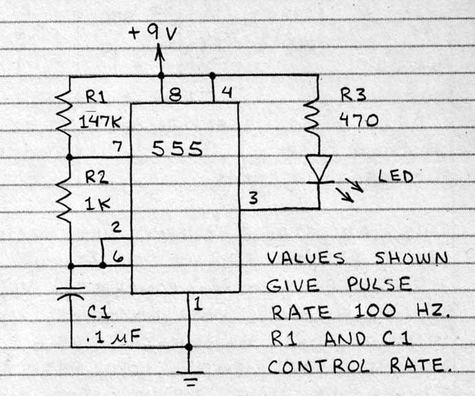
The following circuit originally published by Forrest Mims was made to drive a LED at a known frequency much as a stroboscope would but with less power. The purpose here was to have a "standard" flashing light source to be used as a measuring instrument when it came time to time certain events where a knowledge of the passage of time was important.
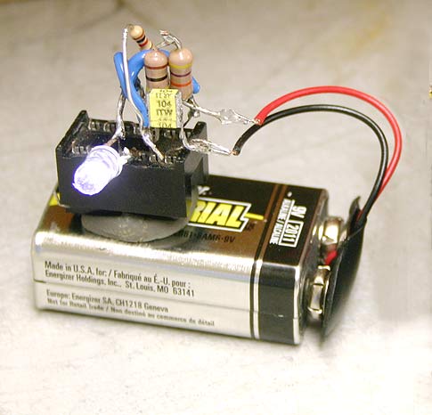
Once the circuit, based on using a 555 Timer IC, was assembled onto a 14 pin IC socket (an 8 pin one could have been used!) the flasher was powered up and somewhat wildly waved about while a a photograph was made of it. The result clearly showed that the flasher was indeed producing bursts of light. In a darkened room these became very evident as persistence of vision made it appear as if these were a series of lights in space as the LED flasher was moved about.
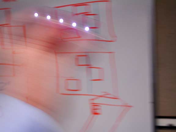
Further, it is noticeable that each individual flash of light must have a very short duration since even while the LED is moving rapidly the individual flashes of light clearly delineate the circular shape of the LED. The duration of each flash can be estimated from a knowledge of the resistance and the capacitance of the components associated with the discharge cycle. All indications are that the duration of each flash is in the microsecond range. Short indeed!
In effect, as the LED is flashing, most of the time it is not producing any light at all since, as you will see later, the time between flashes if much longer than the "on" time of the LED.
Ultimately the purpose for this kind of light source should be mentioned. For example, one might like to know how long an event lasted or the time between the order of arrival at a finish line between racers or the duration of an explosion, the velocity of something or a discharge of light from a flash, etc. When photographs are made from which a determination of elapsed time will be desired having some kind of standard timing information included in the photograph becomes important and useful. How this is done is the subject of other articles.
The circuit shown here is simple to make and it provides a flashing rate of about 100 fps or 1/100 between flashes of the high intensity LED by careful adjustment of the resistor located between pins 7 and 8. In my case I found that about 147 Kohms of resistance between these pins gave me about 100 Hz flashing rate. Actually, making this a variable resistor allows for the adjustment of flashing frequency of the device. A 100 Hz rate is useful as it allows for easy application when timing relationships and ratios need to be determined.
I have found that the current limiting resistor R3 can probably be omitted (I have done so) as at the frequencies and durations that the flasher is used at the LED does not experience too much stress without it and the flashing behavior is more evident. I also found that it seems the frequency is temperature dependant. Ultimately note this is a very simple flasher and even if not perfect in terms of accurate frequency, in an educational application it is the concept, idea, that really matters.
As mentioned above it can be proven that this is a flashing light source by the simple expedient of panning the camera across the LED. One will notice that the LED leaves a discrete set of images of itself from one side of the frame of the other as shown here.
 But one might also be
interested
in "calibrating" the flashing LED
source and this sometimes is a difficult task if one does not have
sophisticated devices such as oscilloscopes, photo tachometers,
stroboscopes, etc.
But one might also be
interested
in "calibrating" the flashing LED
source and this sometimes is a difficult task if one does not have
sophisticated devices such as oscilloscopes, photo tachometers,
stroboscopes, etc.
However, for improvised calibration purposes, the suggestion here is to assume that your camera's shutter has been set or calibrated properly at the camera factory. This is not always exactly the case but the shutter speed accuracy of modern electronically controlled shutters is generally very good.
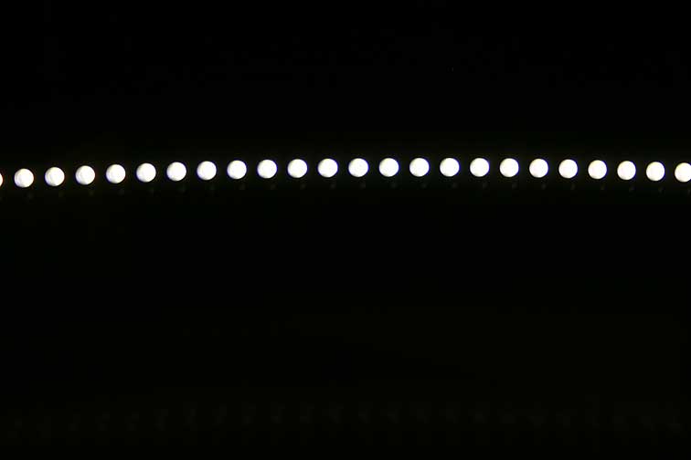
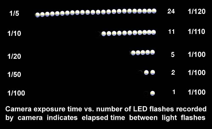
This then opens the door to using the camera's shutter as a device with which to measure the flashing rate of the electronic circuit. This is done by panning or sweeping the image of the LED across the sensor of the camera setting the camera's shutter to relatively long exposure times during which time the image of the LED light is moved across the frame of the camera. The resulting picture might look as shown below. Note that with each decrease in exposure time the LED flasher leaves fewer light impressions on the resulting photograph. The ones shown here were taken separately and then aligned so they would easily illustrate the point that even qualitatively one can deduce that with a halving of exposure time there will be recorded only one half as many flashes.
 Since one can't be sure exactly
when the first and last flash of light is produced by the LED there is
a small amount of ambiguity as to the precise timing of the rate.
In general the first image
of the LED is basically "time zero" and serves as a reference for
timing the rest of the images. In this case one image would be
subtracted from a "train" of them and the rest divided by the exposure
time to determine the flashing rate. It is, however, problematic
to
subtract one image when all one has is one of them and it was made as
in this case at 1/100 second.
Since one can't be sure exactly
when the first and last flash of light is produced by the LED there is
a small amount of ambiguity as to the precise timing of the rate.
In general the first image
of the LED is basically "time zero" and serves as a reference for
timing the rest of the images. In this case one image would be
subtracted from a "train" of them and the rest divided by the exposure
time to determine the flashing rate. It is, however, problematic
to
subtract one image when all one has is one of them and it was made as
in this case at 1/100 second.
So a second approach is to assume that all the images were made within the exposure time period and therefore use them all and divide by the exposure time to find the flashing rate of the LED. The discrepancy is not very great between the two methods and the accuracy generally increases with increases in exposure time. Of course, the assumption is made that the camera shutter is delivering accurately metered times.
So it is granted that the accuracy of frequency measurement depends on the accuracy of the camera shutter and the likelihood of capturing all the flashes possible within the time the shutter is open but the errors tend to be small.
By lighting up the LED lamp with a tungsten source and capturing a continuous record within which exists the flashing record may lead to more precise timing information, although still subject to shutter timing errors, but that is the subject for a follow-up article or you can try it!
From the above material we can tell that the flashing LED is producing a series of bursts at a rate of close to 100 flashes per second and thus the time between flashes is 1/100 second. This kind of "time resolution" or timing information can later be used to advantage when timing other events.
Aside: As I mentioned earlier it did not seem to matter if the 470 ohm "safety" resistor at the LED was included or not. Without it the brightness of the LED flashes is a bit higher so I have one flasher with the resistor in and another with it missing. The one without is still functioning well.
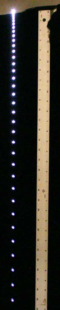 It
is now time to start to think of potential applications
for this flashing
LED light source. I am thinking that it could be dropped from a
particular point into a net of some kind. As the device falls it
would accelerate and this would increase the distance between
images. This would make a photographic record useful possibly to
determine acceleration due to gravity by
including a scale or yardstick next to the falling LED flasher. In
fact, I may make one of these myself in the near future! Which was my
statement in the past as to the left here you can see that I follwed up
on my own suggestion.
It
is now time to start to think of potential applications
for this flashing
LED light source. I am thinking that it could be dropped from a
particular point into a net of some kind. As the device falls it
would accelerate and this would increase the distance between
images. This would make a photographic record useful possibly to
determine acceleration due to gravity by
including a scale or yardstick next to the falling LED flasher. In
fact, I may make one of these myself in the near future! Which was my
statement in the past as to the left here you can see that I follwed up
on my own suggestion.
Images for Science, Industry and Education
The following circuit originally published by Forrest Mims was made to drive a LED at a known frequency much as a stroboscope would but with less power. The purpose here was to have a "standard" flashing light source to be used as a measuring instrument when it came time to time certain events where a knowledge of the passage of time was important.
Once the circuit, based on using a 555 Timer IC, was assembled onto a 14 pin IC socket (an 8 pin one could have been used!) the flasher was powered up and somewhat wildly waved about while a a photograph was made of it. The result clearly showed that the flasher was indeed producing bursts of light. In a darkened room these became very evident as persistence of vision made it appear as if these were a series of lights in space as the LED flasher was moved about.
Further, it is noticeable that each individual flash of light must have a very short duration since even while the LED is moving rapidly the individual flashes of light clearly delineate the circular shape of the LED. The duration of each flash can be estimated from a knowledge of the resistance and the capacitance of the components associated with the discharge cycle. All indications are that the duration of each flash is in the microsecond range. Short indeed!
In effect, as the LED is flashing, most of the time it is not producing any light at all since, as you will see later, the time between flashes if much longer than the "on" time of the LED.
Ultimately the purpose for this kind of light source should be mentioned. For example, one might like to know how long an event lasted or the time between the order of arrival at a finish line between racers or the duration of an explosion, the velocity of something or a discharge of light from a flash, etc. When photographs are made from which a determination of elapsed time will be desired having some kind of standard timing information included in the photograph becomes important and useful. How this is done is the subject of other articles.
The circuit shown here is simple to make and it provides a flashing rate of about 100 fps or 1/100 between flashes of the high intensity LED by careful adjustment of the resistor located between pins 7 and 8. In my case I found that about 147 Kohms of resistance between these pins gave me about 100 Hz flashing rate. Actually, making this a variable resistor allows for the adjustment of flashing frequency of the device. A 100 Hz rate is useful as it allows for easy application when timing relationships and ratios need to be determined.
I have found that the current limiting resistor R3 can probably be omitted (I have done so) as at the frequencies and durations that the flasher is used at the LED does not experience too much stress without it and the flashing behavior is more evident. I also found that it seems the frequency is temperature dependant. Ultimately note this is a very simple flasher and even if not perfect in terms of accurate frequency, in an educational application it is the concept, idea, that really matters.
As mentioned above it can be proven that this is a flashing light source by the simple expedient of panning the camera across the LED. One will notice that the LED leaves a discrete set of images of itself from one side of the frame of the other as shown here.
But one might also be
interested
in "calibrating" the flashing LED
source and this sometimes is a difficult task if one does not have
sophisticated devices such as oscilloscopes, photo tachometers,
stroboscopes, etc. However, for improvised calibration purposes, the suggestion here is to assume that your camera's shutter has been set or calibrated properly at the camera factory. This is not always exactly the case but the shutter speed accuracy of modern electronically controlled shutters is generally very good.
This then opens the door to using the camera's shutter as a device with which to measure the flashing rate of the electronic circuit. This is done by panning or sweeping the image of the LED across the sensor of the camera setting the camera's shutter to relatively long exposure times during which time the image of the LED light is moved across the frame of the camera. The resulting picture might look as shown below. Note that with each decrease in exposure time the LED flasher leaves fewer light impressions on the resulting photograph. The ones shown here were taken separately and then aligned so they would easily illustrate the point that even qualitatively one can deduce that with a halving of exposure time there will be recorded only one half as many flashes.
Since one can't be sure exactly
when the first and last flash of light is produced by the LED there is
a small amount of ambiguity as to the precise timing of the rate.
In general the first image
of the LED is basically "time zero" and serves as a reference for
timing the rest of the images. In this case one image would be
subtracted from a "train" of them and the rest divided by the exposure
time to determine the flashing rate. It is, however, problematic
to
subtract one image when all one has is one of them and it was made as
in this case at 1/100 second.So a second approach is to assume that all the images were made within the exposure time period and therefore use them all and divide by the exposure time to find the flashing rate of the LED. The discrepancy is not very great between the two methods and the accuracy generally increases with increases in exposure time. Of course, the assumption is made that the camera shutter is delivering accurately metered times.
So it is granted that the accuracy of frequency measurement depends on the accuracy of the camera shutter and the likelihood of capturing all the flashes possible within the time the shutter is open but the errors tend to be small.
By lighting up the LED lamp with a tungsten source and capturing a continuous record within which exists the flashing record may lead to more precise timing information, although still subject to shutter timing errors, but that is the subject for a follow-up article or you can try it!
From the above material we can tell that the flashing LED is producing a series of bursts at a rate of close to 100 flashes per second and thus the time between flashes is 1/100 second. This kind of "time resolution" or timing information can later be used to advantage when timing other events.
Aside: As I mentioned earlier it did not seem to matter if the 470 ohm "safety" resistor at the LED was included or not. Without it the brightness of the LED flashes is a bit higher so I have one flasher with the resistor in and another with it missing. The one without is still functioning well.
It
is now time to start to think of potential applications
for this flashing
LED light source. I am thinking that it could be dropped from a
particular point into a net of some kind. As the device falls it
would accelerate and this would increase the distance between
images. This would make a photographic record useful possibly to
determine acceleration due to gravity by
including a scale or yardstick next to the falling LED flasher. In
fact, I may make one of these myself in the near future! Which was my
statement in the past as to the left here you can see that I follwed up
on my own suggestion.